VORTEX FLOW METER Model FM 36
Home » Products » VORTEX FLOW METER Model FM 36
VORTEX FLOW METER Model FM 36
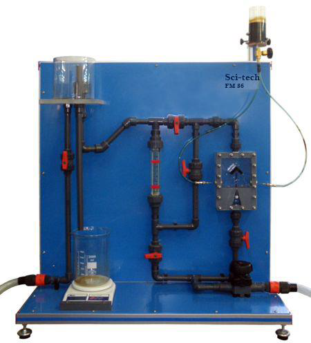
Sci-tech Vortex Flow Meter Model FM 36 makes it possible to study different methods of volumetric and mass flow measurement, as well as to compare continuous and intermittent methods. This module includes two continuous and two intermittent methods to carry out the experiments. The continuous methods include a vortex flowmeter and a variable-area flowmeter (or rotameter). A series of oscillating vortices, where the oscillating frequency is proportional to the flow rate, are generated in the vortex flowmeter. Dye or colouring is used to visualize such vortices. Intermittent methods include the measurement of volumetric and mass flows. A precision scale is used to measure the mass flow and compare the measurements. The water supply may be provided either from the Hydraulics Bench FM100 or from external source.
| Size: | 70cm x 60cm x 90cm (LxWxH) |
| Weight: | 35 kg |
Item Description
Sci-tech Vortex Flow Meter Model FM 36 makes it possible to study different methods of volumetric and mass flow measurement, as well as to compare continuous and intermittent methods. This module includes two continuous and two intermittent methods to carry out the experiments. The continuous methods include a vortex flowmeter and a variable-area flowmeter (or rotameter). A series of oscillating vortices, where the oscillating frequency is proportional to the flow rate, are generated in the vortex flowmeter. Dye or colouring is used to visualize such vortices. Intermittent methods include the measurement of volumetric and mass flows. A precision scale is used to measure the mass flow and compare the measurements. The water supply may be provided either from the Hydraulics Bench FM100 or from external source.
The vortex flow meter is installed in the water circuit of the Hydraulics Bench FM100 trainer. It operates according to the principle of Von Karman vortex shedding. Downstream of a dam body in a flow, vortices alternately form which are separated off by the flow. The frequency of the vortex separation to both sides of the dam body is proportional to the flow rate. The separated vortices alternately generate local vacuum which is measured using capacitive pressure sensors. The pressure signals are converted and indicated as the flow rate on a display. The necessary connections are provided so that the pressure loss can be determined with the Hydraulics Bench FM100.
See also different:

Sci-tech Multi-stage Centrifugal Compressor Demonstration Apparatus Model FM 099 allows the students to measure the operation characteristics of a multistage centrifugal compressor. For that purpose, the unit carries out the actual measurement [...]


