
Flow Meter Demonstration Apparatus MODEL FM 18
Flow Meter Demonstration Apparatus MODEL FM 18
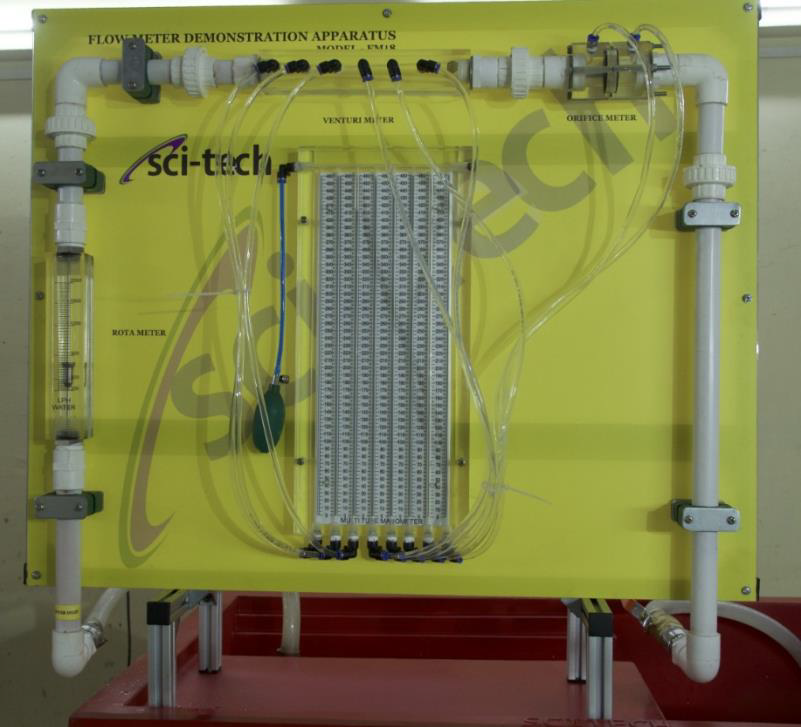
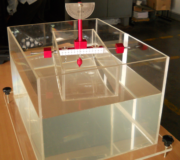
The Sci-tech Flow Meter Demonstration Apparatus Model FM 18 is a mobile bench top unit and has been designed to demonstrate the working of the venture meter, orifice plate and the turbine flow meter. The apparatus consists of a piping network with flow meters located suitably and instrumented with static pressure taps. Provision is made to calibrate and determine the co-efficient of discharge of venture meter and orifice plate. The turbine flow meter is used as a reference. The flow meters are calibrated by static pressure measurements using manometers and actual flow measurements using graduated measuring tank of the hydraulic bench. Wall pressure tapings are provided along the converging and diverging portions of the venture-meter to measure the static pressure distribution. Multi-tube manometer having a manifold with an air bleed valve is supplied to make static pressure measurements. The manometer is pressurized by a hand pump.
| Size: | 60cm x 40cm x 80cm (LxWxH) |
| Weight: | 25 kg |
Item Description
Various devices are available to measure the fluid flow rate. Majority of these devices use the Bernoulli’s theorem which states that the sum of pressure head, velocity head and the potential head is constant along a stream line for a steady, in viscid and incompressible flow of fluid. Measurement of fluid flow rate is important to the students of mechanical, chemical, civil and several other branches of engineering.
The Sci-tech Flow Meter Demonstration Apparatus Model FM 18 is a mobile bench top unit and has been designed to demonstrate the working of the venture meter, orifice plate and the turbine flow meter. The apparatus consists of a piping network with flow meters located suitably and instrumented with static pressure taps. Provision is made to calibrate and determine the co-efficient of discharge of venture meter and orifice plate. The turbine flow meter is used as a reference. The flow meters are calibrated by static pressure measurements using manometers and actual flow measurements using graduated measuring tank of the hydraulic bench. Wall pressure tapings are provided along the converging and diverging portions of the venture-meter to measure the static pressure distribution. Multi-tube manometer having a manifold with an air bleed valve is supplied to make static pressure measurements. The manometer is pressurized by a hand pump.
Water is supplied by a hose connection to the inlet and flow rate is varied by a valve at the outlet. The complete unit is manufactured from corrosion resistant materials. The FM100 Hydraulic Bench or any other standard hydraulic bench models can be used to supply water.
OPTIONS:
- Test Rig for Calibration of different flow meters:
The Test Rig can be used for calibrating different flowmeters like venture meter, orifice meter, rotameter etc. The flowmeter to be calibrated can be fitted to the apparatus. The apparatus will be have a master flow sensor with accuracy of +/-2% which can be used a reference for calibration of flowmeter.
Recommended options – 1st with differential pressure transmitter & other with conventional u tube manometer.
Technical Specifications
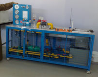
SPECIFICATIONS FOR FLOW METER CALIBRATION APPARATUS
Option 1: Apparatus with Turbine Type Flow Senor & Differential Pressure Transmitter
- Flow Sensor: Type Turbine type flow sensor, MOC S.S. 304. Accuracy:+/-2% FSD, pressure: 10 kg/cm2, Temp: 100C,
- With panel mount indicator
- Differential Pressure Transmitter: Range 0-100mm WC, Output 4-20 mA with panel mount indicator.
- Rotameter: Range: 200-2000LPH
- Venturimeter: Made in Acrylic, Inlet & Outlet diameter 25 mm, Throat Diameter 16mm
- Orificemeter: Made in Acrylic, Inlet & Outlet diameter 25 mm, Throat Diameter 15mm
- Sump Tank: 100Ltrs, Made in PVC
- Base Frame: Made in MS Square pipes & Sheet, Welded, Powder painted.
- Piping: Non corrosive PVC Piping with unions to fit desired flow meter to be calibrated.
Option 2: Apparatus with Turbine Type Flow Senor & U Tube Manometer
- Flow Sensor: Type Turbine type flow sensor, MOC S.S. 304. Accuracy:+/-2% FSD, pressure: 10 kg/cm2, Temp: 100C,
- With panel mount indicator
- U tube mercury manometer: Range 0-500 mm, monomeric fluid- Mercury.
- Rotameter: Range: 200-2000LPH
- Venturimeter: Made in Acrylic, Inlet & Outlet diameter 25 mm, Throat Diameter 16mm
- Orificemeter: Made in Acrylic, Inlet & Outlet diameter 25 mm, Throat Diameter 15mm
- Sump Tank: 100Ltrs, Made in PVC
- Base Frame: Made in MS Square pipes & Sheet, Welded, Powder painted.
- Piping: Non corrosive PVC Piping with unions to fit desired flow meter to be calibrated.
Important Features and Specifications:
1. Piping system, 25mm nominal bore, and stainless steel.
2. Venturimeter, transparent, made of clear Acrylic and having convergent and divergent portions, throat diameter: 15mm, maximum diameter: 31.75mm, upstream taper: 210, downstream taper: 140. No. of static pressure taps: 7.
3. Orifice plate, 20mm nominal diameter.
4. Turbine flow meter, 2 – 20 liters/min, max. flow rate.
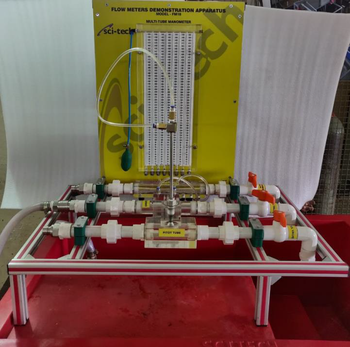
5. Multi-tube manometer, 0-440 mm water column, No. of tubes: 8 with hand pump.
Options:
1. Other types of water flow measuring devices such as (a) Sudden Enlargement, (b) Elbow (c) Variable Area Rotameter (d) Nozzle and (e) Pitot-tube with necessary pressure instrumentation can be included in the apparatus to suit the requirements of the user on request.
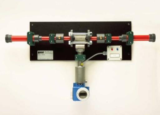
Specifications of Vortex Flow Meter:
[1] vortex flow meter as accessory for FM 18 trainer
[2] operation according to Von Karman vortex shedding
[3] display indicating flow rate
[4] connections to facilitate pressure loss measurement with the FM 18
[5] connections to supply auxiliary power via the FM 18
[6] vertical and horizontal installation possible.
Technical Data of Vortex Flow Meter:
1) Max. flow rate: 5200L/h
2) Auxiliary power: 24VDC
3) Pipe connections: DN 32
OPTIONS:
1) Test Rig for Calibration of different flow meters:
The Test Rig can be used for calibrating different flowmeters like venture meter, orifice meter, rotameter etc. The flowmeter to be calibrated can be fitted to the apparatus. The apparatus will be have a master flow sensor with accuracy of +/-2% which can be used a reference for calibration of flowmeter.
Recommended options – 1st with differential pressure transmitter & other with conventional u tube manometer.
Services Required
1. Water Supply.
2. Electrical Supply, 240 V, single-phase, 50 Hz.
Overall Dimensions
Height: 0.75m, Width: 0.45m, Length: 0.95m.
The manual describing the theoretical and practical aspects of the apparatus, operation, analysis of results, and sample of results will be supplied with the equipment.
Model Number
FM 18
See also different:
Sci-tech Metacentric Height Apparatus Model FM 08A demonstrates the metacentric height of a floating body and the height variation is used with Hydraulic Bench Model MH100 or a separately supplied bowl. The equipment consists of a rectangular [...]
Sci-tech Pumps Comparison Apparatus Model FM 95 includes two centrifugal pumps, one piston pump as a positive-displacement pump and a self-priming side-channel pump. The side-channel pump works primarily as a centrifugal pump and, depending on [...]
Sci-tech Permeability / Fluidization Studies Apparatus Model FM 63 is designed to study characteristics of flow through bed of particles. The apparatus consists of a cylinder filled with various type of bed granular medium (for example, sand), [...]