Visualization of Streamlines MODEL FM 133
Visualization of Streamlines MODEL FM 133
The laminar, two-dimensional flow in Sci-tech Visualization of Streamlines Model FM 133 is a good approximation of the flow of ideal fluids: the potential flow.
Item Description
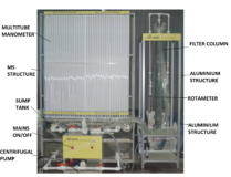
FM 133 can be used to visualize streamline fields for flows around drag bodies and flow through changes in cross section. The streamlines are displayed in colour by injecting a contrast medium (ink). Sources and sinks are generated via four water connections in the bottom plate. The streamlines can be clearly observed through the glass plate during flow around and flow through.
The water flow rate and the quantity of contrast medium injected can be adjusted by valves. The water connections are also activated by valves and can be combined as required. Individual models can be cut out of a rubber plate that is included.
The experimental unit is positioned easily and securely on the work surface of the FM 100F base module. The water is supplied by FM 100F. Alternatively, the experimental unit can be operated by the laboratory supply.
Features
Visualization of streamlines
Ink as a contrast medium
Various models included: drag bodies and changes in cross-section
Sources and sinks, individually or in combination
Technical Specifications
Specifications
1. Visualization of streamlines
2. Water as flowing medium and ink as contrast medium
3. Upper glass plate, hinged for interchanging models
4. Bottom plate with water connections for generating sources/sinks
5. Sources/sinks can be combined as required
6. Different drag bodies and changes in cross-section included
7. Rubber plate for creating your own models included
8. Flow velocity, water supply and water drain in sources/sinks as well as dosage of the contrast medium can
be adjusted by using valves
9. Water supply using FM 100F base module or via laboratory supply
Technical Specifications
Flow chamber contains two plates
distance between the plates: 2mm
upper plate made of glass
bottom glass plate with four water connections for sources/sinks
size experiment area: LxW: 400x280mm
10 drag bodies and changes in cross-section
Rubber plate for your own models
LxH: 300x400mm
thickness: 2mm
Injection of the contrast medium (ink)
15 holes
Tank for contrast medium: 500mL
Experiments
visualisation of streamlines in
flow around drag bodies
flow through changes in cross-section
influence of sources and sinks
Mains Power
220 – 240V 1Ph, 50Hz
See also different:
Sci-tech Radial Flow Turbine Model FM 24 includes a turbine rotor fitted with four nozzle-shaped exits. The rotor is mounted in a transparent housing. The air flows through the exit nozzles of the turbine rotor, expands and accelerates. The ex [...]
Sci-tech Flow of Bulk Solids from Silos Apparatus Model FM 120 provides a practical demonstration of the types of discharge from different silos: mass flow, funnel flow and arching. The type of discharge that occurs is dependent on the flow pr [...]