Strength of Materials Modular Experiments Kit Model MT 146
Home » Products » Strength of Materials Modular Experiments Kit Model MT 146
Strength of Materials Modular Experiments Kit Model MT 146
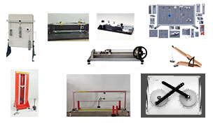
Sci-tech Strength of Materials Modular Experiments Kit Model MT 146 is a complete package in Engineering Science experiments. The full set includes the mobile trolley, a full set of Strength of Materials kits; work panels and a spares kit. This full set allows at least three sets of students to work with any three of the Engineering Science experiments at the same time, while storing the other kits tidily and efficiently. Alternatively, lecturers or teachers may set up one experiment as a demonstration on the mobile trolley while two groups of students do experiments at their desks. The kit helps to replace the common smaller parts of the kits that may get lost over time. The trolley also includes some empty trays, useful for storing coursework, worksheets or guidance notes.
Size: | 120cm x 80cm x 80cm (LxWxH) |
Weight: | 55 kg |
Item Description
Feature
• A mobile and compact trolley holding a full set of ‘Strength of Materials modular kits’ andthree work panels for over 60 experiments in fundamental engineering science topics
• All the parts needed in one mobile frame – one person can move a full set of kits from one room to another
• Includes a spares kit to replace common parts that could become lost from experiments during use
• Spare empty trays to store additional material such as coursework, worksheets or guidance notes
• Strong, lockable wheels on the trolley allow easy movement but also hold the trolley stable when needed –making it an ideal demonstration table
• Flat top with fixing positions for storage of the work panels
Sci-tech Strength of Materials Modular Experiments Kit Model MT 146 is a complete package in Engineering Science experiments.
The full set includes the mobile trolley, a full set of Strength of Materials kits; work panels and a spares kit.
This full set allows at least three sets of students to work with any three of the Engineering Science experiments at the same time, while storing the other kits tidily and efficiently. Alternatively, lecturers or teachers may set up one experiment as a demonstration on the mobile trolley while two groups of students do experiments at their desks.
The kit helps to replace the common smaller parts of the kits that may get lost over time. The trolley also includes some empty trays, useful for storing coursework, worksheets or guidance notes.
Technical Specifications
Specifications
Experiment Modular Kits
- Forces Kit Module MT 146-01
Demonstrates how to find the centre of gravity of shapes and the relationship between angles and coplanar forces, using force triangles.
This versatile kit is part of a series that allows many experiments using different arrangements of their parts. Students, teachers or lecturers fit the parts of the kit to the work panel (supplied separately) to study or show an engineering science topic.
This kit includes a set of different plastic shapes for experiments in centres of gravity of two-dimensional objects. It also includes pulleys, weights and a magnetic protractor for experiments in concurrent and nonconcurrent coplanar forces and angles. force triangles, polygons and linked polygons. The guidance notes show how to analyse and predict forces
using Bow’s Notation and the parallelogram of forces.
The selection of parts in the kits and the choice of fixing points on the work panel means that teachers or lecturers may extend the experiments to an even greater range.
Experiments:
- Centre of gravity
- Force triangles
- Force polygons and Bow’s notation
- Linked polygons (non-concurrent forces)
- Moments Kit Module MT 146-02
Demonstrates the relationship between distances and forces in rigid beams and levers demonstrating the first, second and third order levers.
This kit includes a rigid beam for experiments in the principle of moments, extending to levers and beams. It shows the three main lever types (1st, 2nd and 3rd order) and includes an ‘L’ shape plate for experiments in bell crank levers. A pulley allows extra experiments with moments caused by oblique forces. The rigid beam allows experiments that show the use of moments to find unknown weights, creating simple beam balances. It also works with spring balances to show reaction forces on beams with point loads and uniformly distributed loads.
Experiments
- Principle of moments
- Beam balances
- 1st, 2nd and 3rd order levers
- Bell crank lever
- Beam reactions
- Deflection of Beams and Cantilevers Kit Module MT 146-03
Demonstrates the deflection of beams of different materials and dimensions, held on different supports, both clamps and knife edges.
This kit includes different beams and fixing blocks. The fixing blocks work as clamps or knife-edge supports. They hold the beams in different ways, such as a cantilever, simply supported, fixed (encastre) and a propped cantilever.
Students set up a beam on the supports and add weights to deflect the beams. An accurate dial indicator measures the deflection at the point of loading.
The choice of different beams allow extra experiments, showing the relationships between beam deflection and ‘I’ (second moment of area) value. They also allow comparisons of different beam material and how it affectsb deflection, introducing Young’s modulus.
Students also use the cantilever for easy experiments showing the relationship between beam length and deflection.
Experiments
- Beam length and deflection
- Beam material and deflection (Young’s modulus)
- Beam ‘I’ value and deflection
- Beam supports (cantilever, propped cantilever, fixed beam and simply supported) and deflection
- Torsion of Circular Sections Kit Module MT 146-04
Demonstrations the torsion in circular section specimens of different materials and lengths.
This kit includes different circular section specimens and adjustable chucks for experiments in torsion.
Students fix the specimens in the chucks and apply weights to a lever arm. The arm applies a moment (torque) to one end of the specimen. A scale on the arm shows the angle of twist.
Standard tests show the relationship between torsion and ‘J’ (polar second moment of area) value. Students use this to predict the twist angle for any given specimen.
The choice of different specimens allows comparisons of different specimen material and how it aff ects torsion, introducing the modulus of rigidity.
Students also move the chuck positions for easy experiments showing the relationship between specimen length and angle of twist.
Experiments
- Specimen length and angle of twist
- Specimen material and angle of twist (modulus of rigidity)
- Specimen ‘J’ value and angle of twist
- Tensile Tester Kit Module MT 146-05
Demonstrates the principles of tensile tests on specimens of different materials, showing material behaviour in the elastic and plastic region (Young’s modulus).
This kit includes a cased tensile tester with specimens of different materials to show students the principles of tensile tests.
Students use the tensile tester to stretch the specimens to destruction, while measuring the extension and force. The tests introduce students to tensile test terms including:
- overall stress and strain
- yield properties
- tensile strength
- elongation
The choice of different specimens allows comparisons of different specimen material and how it affects its tensile properties.
Experiments
- Tensile tests (to destruction) of different materials
- Finding the tensile strength of a material
- Material behaviour in the elastic and plastic region
- Creating a force and extension chart
- Simple Harmonic Motion Kit Module MT 146-06
Demonstrates simple harmonic motion (oscillation) in springs and pendulums, and its usefulness.
This kit includes different pendulums and a spring to show students the principles and use of simple harmonic motion. Students test different pendulums and a spring to see how different factors, such as mass or pendulum length affect simple harmonic motion and the period of oscillation.
The theory shows how to predict the period of oscillation for a given pendulum or spring for comparison with actual results. The kit includes an experiment with the Kater’s pendulum that shows the relationship between simple harmonic motion and gravity, for prediction of gravity to a reasonable accuracy.
The kit also has introduces students to a simple ‘spring rate’ test, and key scientific terms such as:
- Moments of inertia
- Parallel axis theorem
Experiments
- Simple harmonic motion of simple, bifilar and trifilar pendulums of different length and mass
- Simple harmonic motion of a spring with different masses, and a simple spring rate test
- Simple harmonic motion of a compound pendulum
- Simple harmonic motion and gravity using a Kater’s pendulum
- Friction and Inclined Plane Kit Module MT 146-07
Demonstrates kinetic and static sliding friction and rolling friction on bodies, and between different surfaces on a flat or inclined plane.
This kit includes parts for experiments in friction and forces on a flat or inclined plane. The plane has an inclinometer and adjustment to allow the student to set the plane to any angle between zero and 90 degrees. The parts include different friction surfaces, a roller set, a rolling car or sled with adjustable mass, and a simple roller.
Students fit the different parts to the plane and apply masses. They learn how different surface finishes and mass affect friction and how surface angles and mass affect forces around a body on a plane.
The experiments introduce students to important engineering and scientific terms, such as the coefficient of friction, sliding friction and kinetic friction.
The inclinable plane allows students to do the classic ‘forces on an inclined plane experiments’. It also shows the relationship between frictional forces and angles other than horizontal.
Experiments
- Forces on an inclined plane
- Rolling and sliding friction on different surfaces
- Kinetic and static sliding friction between different surfaces
- Surface angle and friction between different surfaces
- Potential and Kinetic Energy Kit Module MT 146-08
Demonstrates the difference between potential and kinetic energy and how it can change from one to the other using a pendulum or flywheel. Also demonstrates elastic potential energy in a spring.
This kit includes a pendulum, a spring and a flywheel for experiments in potential and kinetic energy. Students test each part to discover the difference between potential and kinetic energy and the transfer of energy from one form to another.
The kit introduces students to key engineering terms such as ‘moment of inertia’ and ‘elastic potential energy’.
Experiments
- Kinetic and potential energy in a pendulum
- Elastic potential energy in a spring
- Kinetic energy in a flywheel
- Pulley Kit Module MT 146-09
Demonstrates the mechanical advantage of different combinations of pulleys and a simple wheel and axle.
This kit includes a wheel and axle with single, double and triple wheel or ‘sheave’ pulleys for experiments in mechanical advantage.
Students test fixed, movable and compound pulleys attached to load and eff ort weights to test their
mechanical advantage.
The kit includes a unique pulley – the Weston Differential pulley to show how two diff erent size sheaves on one pulley has a dramatic effect on mechanical advantage.
The kit introduces students to key engineering terms such as machine efficiency, velocity ratio and ‘work done’.
Experiments
- Simple pulleys – fixed, movable and compound
- The wheel and axle
- The Weston differential pulley
- Drive Systems Kit Module MT 146-10
Demonstrates the advantages and disadvantages of three popular drive systems: belt, chain and a universal coupling, using a manually rotated frame with a low-friction cantilever linkage, adjustable masses and a spring to apply force.
This kit includes three different drive systems to show their relative advantages and disadvantages.
Students test a universal coupling, a belt drive and a chain drive to see how they work and how they differ in the way they transfer motion (power).
The kit includes extra parts to help show the importance of the angle of lap around a pulley and its relationship with friction.
The kit introduces students to key engineering terms such as gear ratio, pulley ratio and efficiency.
Experiments
- Power transfer, efficiency and direction in a belt drive
- Power transfer and efficiency in a chain drive
- Input and output relationships of a universal coupling
- Friction and angle of lap on a pulley
- Cam, Crank and Toggle Kit Module MT 146-11
Demonstrates the characteristics of a mechanical toggle, crank motion and the most popular shaped cams: pear, heart, round and snail.
This kit includes a crank and slider to show the relative forces during crank motion. It also includes four popular cam shapes to show their different characteristics.
Another set of parts in the kit shows the characteristics of a mechanical toggle.
Students fit the crank and slider with weights and a spring balance to see the change in linear and rotational forces (moments) as the crank turns. They also use the slider with different followers on a set of four popular shape cams -heart, pear, spiral and round. This gives several cam and follower combinations to help students understand the different characteristics of each cam and why engineers choose between them for different applications.
The last set of parts in the kit has a simple linkage that allows students to see the characteristics of a toggle mechanism. Its shows the relative forces and angular conditions of the toggle in its initial state and how they affect the point at which it locks or ‘snaps’ into a horizontal state.
The kit introduces students to key engineering terms such as a ‘flat follower’, a ‘roller follower’ and ‘toggle action’.
Experiments
- Displacement and angle characteristics of pear, heart, round and spiral cams
- Characteristics of a mechanical toggle
- Turning moments and forces during crank motion
- Gear Trains Kit Module MT 146-12
Demonstrates the characteristics of a spur gear, bevel gear and a worm drive.
This kit includes a selection of different gears for experiments to find their unique characteristics.
drive. The spur gears have two sets of teeth on the same shaft, allowing extra experiments in compound gear trains.
Students test each set of gears to see how it works and note the differences in characteristics (such as efficiency, gear ratio and mechanical advantage) of each set.
The gear sets are a selection of the most common sets similar to those used in real applications, such as automobile gear boxes, domestic and industrial hand tools and clockwork instruments. Each has advantages and disadvantages that make them suitable for a particular job.
The kit introduces students to key engineering terms such as gear ratio, efficiency, mechanical advantage and velocity ratio.
Experiments
- Characteristics of spur gears, including single and compound gear trains and the ‘idler’ gear
- Characteristics of a bevel gear
- Characteristics of a worm drive
- Simple Mechanisms Kit Module MT 146-13
Demonstrates how the scotch yoke, crank and slider and quick return mechanisms convert motion.
This kit includes three popular mechanisms for experiments in conversion of motion from linear to rotary, or rotary to linear. These include the Scotch yoke (sometimes called ‘donkey crosshead’ or ‘slotted link’), the crank and slider, and the quick return mechanism.
Students test each mechanism to see how it works and note the differences in the way that each mechanism converts the motion.
The three mechanisms are the same as those used in real applications, such as combustion engines, power assisted valves or fluid pumping systems. Each has a unique way of converting motion, shown by the experiments.
The kit introduces students to key engineering terms such as reciprocating motion, rotary to linear motion and linear to rotary motion.
Experiments
- Conversion of motion using the ‘Scotch yoke’ (or ‘slotted link’)
- Conversion of motion using the quick return mechanism
- Conversion of motion using the crank and slider
- Bar Linkages Kit Module MT 146-14
A set of bars and pivot joints for students to understand different bar linkages and mechanisms.
This kit includes a selection of over 20 perforated bars of different lengths and pivots or ‘joints’ to allow students to create an unlimited choice of linkages.
The kit includes magnetic ‘wipeable’ sheets and holders for non-permanent markers so the student can trace the relative movements of the linkages or joints.
The kit introduces students to key engineering terms such as four-bar linkages, rotary and linear movement, and planar linkages.
Experiments
- Four-bar linkages – crank rocker, double rocker, drag link and parallelogram
- Straight line linkages – Watt’s straight line, Chebyshev, Peaucellier-Lipkin, Hart’s inversor, Robert’s and Hoeken’s
- Pantograph
- Ackermann steering
- Centrifugal Force Kit Module MT 146-15
Demonstrates the relationship between centrifugal force, radius and velocity of rotating masses.
This kit includes a manually rotated frame with a low friction cantilever linkage. The frame has mounting positions for adjustable masses and a spring that applies a fixed frictional force value to a rotating drum. The range of mounting positions and masses allows many variations of the experiment to help students understand the relationships between the variables of speed, mass and radial position.
Students fit the chosen masses to one side of the frame and an equal counterbalance to the opposite side of the frame. They rotate the assembly which will overcome the spring frictional force at a given speed, working as centrifugal clutch that regulates its own speed. The frame has a durable ‘clicking’ tab that students use with a stopwatch (supplied) to measure the speed. They use their measurements to calculate the forces due to the rotating masses and compare them with the opposing force from the spring.
The kit introduces students to key engineering terms such as centrifugal and centripetal force, while explaining the fictitious term ‘centrifugal’ force and its accepted use.
It also shows the use of ‘radians’ in rotational velocity measurement.
Experiments
- Relationship between centrifugal force, radius and
velocity of different rotating masses
- Rotational Friction Kit Module MT 146-16
Demonstrates how rotational friction affects the efficiency of popular machine elements, including a screw jack, wedge and different bearings.
This kit includes a screw jack (or ‘jackscrew’), a wedge and different bearings. It helps students understand how rotational friction affects the efficiency of popular machine elements and bearing materials. It shows why engineers choose some materials and devices above others for any given application.
Students fi t the parts to the work panel and apply eff ort and load weights to find their relative mechanical advantage and efficiency.
The kit introduces students to key engineering terms such as:
- Mechanical advantage
- Velocity ratio
- Efficiency
- ‘Overhaul’
Experiments
- Efficiency of a screw jack
- Efficiency of a wedge
- Efficiency of different bearings
- Geneva & Ratchet Mechanisms Kit Module MT 146-17
Demonstrates how the Geneva mechanism and a ratchet mechanism convert motion.
This kit includes two popular mechanisms for experiments in conversion of motion from one form to another. These include the Geneva mechanism (sometimes called the Maltese cross mechanism or crank and star), and a ratchet mechanism.
Students test each mechanism to see how it works and note the differences in the way that each mechanism converts the motion.
The two mechanisms are the same as those used in real applications, such CNC machines, hand tools, turnstiles and lifting hoists. Each has a unique way of converting motion, shown by the experiments.
Experiments
- Conversion of motion using the Geneva mechanism
- Conversion of motion using a ratchet
- Spring Tester Kit Module MT 146-18
Demonstrates the characteristics of coiled springs and how to test them (Hooke’s law).
This kit includes different coiled springs for experiments in spring testing. These include extension springs, compression springs, parallel springs and springs that can connect in series.
Students test the springs to prove Hooke’s law and find their spring rate, comparing it with given manufacturer’s values. They also test springs in parallel and series to see how this affects the overall spring rate.
The kit helps students to understand the link between spring rate, spring extension and the design and construction of springs. It introduces students to key engineering terms such as:
- Spring rate
- Hooke’s Law
- Spring pretension
Experiments
- Hooke’s law and compression spring tests
- Hooke’s law and extension spring tests
- Parallel and series spring tests
Supply includes:
- Mobile trolley x 1
- Work Panels x 3
- All 18 Engineering Science experiment kits
- Spares Kit x 1
- Empty trays x 5
Model Number
MT 146
See also different:
Sci-tech Saturation Pressure Unit Model BSG 020 consists of a water boiler, including a Sci-CalR computer-controlled immersion heating element, and a sight glass to observe the boiling patterns in the water surface and control the water level [...]
Sci-tech Temperature Regulation & Control Trainer Model PCU 056 consists of four clearly differentiated parts : ● Hydraulic circuit consisting of a lower tank and an upper tank, one centrifugal pump, one flow-meter, three open / closed sol [...]