Power Engineering Trainer Model ELTR 026
Home » Products » Power Engineering Trainer Model ELTR 026
Power Engineering Trainer Model ELTR 026
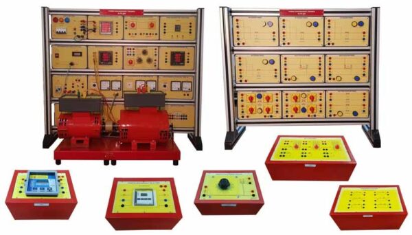
- Each of following independent PET trainer may need a few set of associated panels (7-8 nos. typically) which are mounted in a light weight sturdy aluminum profile flat demo panel system.
- Facilitates easy and safe wiring by students due to use of 4mm sturdy Shrouded banana patch cords and shrouded socket arrangements for high voltage circuits
- Each panel has ABS molded plastic sturdy enclosure, and colorful screw-less overlays showing circuits diagrams & its connection tag numbers for easy understanding and connection 4. Set of Instructor Guide & Student Workbook.
Item Description
Choice of Power Engineering Trainer PET-1: Select one or more trainer.
| Model Name Specifications | PSS/Gen Generation & Transformer | PET/TL Transmission line |
PET/SSD Substation Switching & Distribution |
|
| Rack Configuration & No. of panels |
4 x 2 (7) | 5 x 2 (7) | 5 x 2 (9) | |
| Resource Panels needed | EMT4, EMT8, EMT9 (3nos). EMT5A/5B, EMT6A/6B, EMT26A/26B, EMT34 | EMT1, EMT34 (2nos) Table Top-EMT38 (2nos). EMT14A/B (dual panel) EMT 15 A/B (dual Panel), P30 phase sequence indicator | EMT41 (9 Nos) | |
| Table Top M/C’s / accessories | Trunnion mounted DC 1 HP shunt machine coupled to 3ph salient pole alternator 1KVA, 415VAC, 50Hz Transformer 1KVA 3ph 415:415VAC 50Hz, | 3 phase dimmer: I/P 415V, 3ph, 50Hz O/P: 0-470V, 3A, 3 | ||
| List of Experiments | 1. Regulation of 3 ph alternator by :
a) Synchronous impedance method b) ZPF or POTIER method c) Actual load test 2. Determination of : a) Direct axis and quadrate axis sub transient reactance Xd” & Xq”. b) Zero sequence reactance X0. c) Negative sequence reactance X2
|
1. Understanding phase sequence of a 3phphase source.
2. Working with bi-directional 3ph AC measurement panel observing flow of real & reactive power & optionally Modbus communication with PC. 5. Load test & calculation of regulation, efficiency of transmission line. 6. Receiving end circle diagram |
To Study following configuration
1. single Bus Configuration 2. Double Bus Double Breaker Configuration 3. Main & Transfer Bus configuration 4. Double Bus Single Breaker Configuration 5. Ring Bus configuration 6. Breaker and a Half Configuration |
|
| Mechanical dimension (mm) / Kg. Wt. | 1170(L) x 300(W) x 990(H)
40Kg. |
1170(L) x 300(W) x 545(H)
40Kg. |
||
| Model Name Specifications | PET/SCADA
Smart PET Optional |
PET/PR-I Protection Relays-I | PET/PR-II Protection Relays -II | |
| Rack. Configuration & No. of panels | 4 x 2 (8) | 4 x 2 | 4 x 2 | |
| Resource Panels needed | Converter cum distribution panel (CDP), Simulation cum extension panel (SEP), Power supply panel-Auxiliary substation power supply 24VDC, Relay Panel. | EMT16, EMT23, EMT39, EMT20F | EMT16, EMT23, EMT39, EMT20F | |
| Table Top M/C’s / accessories | Select one or more of the following IDMT over current Relay Over / under voltage Relay Earth Fault Relay Differential Relay |
Select one or more of the following Reverse power relay Under/over frequency relay Phase balance / sequence relay Power factor relay Distance Relay |
||
| List of Experiments | Study of; DCS consisting of PLC networked over RS485 with MultiDrop SCADA S/W [Supplied on Installable CD] with MODBUS capability USB H/W lock. Protection Relay [optionally MODBUS RS485 configurable] PLC receives trip contact from protection relays, circuit breakers & provides trip outputs to circuit breaker between various power substations like generation transformer transmission line substation switching network etc. |
To plot characteristics curve / behavior | To plot characteristics curve/ behavior | |
| Mechanical dimension (mm) / Kg. Wt. | 960(L) x 300(W) x 545(H) | 960(L) x 300(W) x 545(H) | 960(L) x 300(W) x 545(H) | |
See also different:

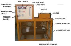
Sci-tech Air-Compressor Test Apparatus Model TH-106 consists of a reciprocating air compressor driven by an electric motor.


