Kinematic model: Ackermann Steering Mechanism Model MT 138
Home » Products » Kinematic model: Ackermann Steering Mechanism Model MT 138
Kinematic model: Ackermann Steering Mechanism Model MT 138
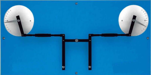
Sci-tech Kinematic model: Ackermann Steering Mechanism Model MT 138 is used to study a steering trapezoid. The experimental unit comprises two track rods with drag link, two track-rod arms and two steering pins, where, in theory, the wheels are attached. The length of the axis corresponds to the distance between the steering pins.
The lengths of the two track rods are independently adjustable.
To set the zero position of the steering angle, the mechanism is fixed via a lock on the drag link. The steering angle on the inside wheel is set; the angle of the outside wheel changes according to the geometry and is read. The difference between the two angles is the lead angle or relative steering angle. The difference between the calculated and measured steering angles is the steering error. Disadvantages of an incorrectly set track rod can be demonstrated.
| Size: | 60cm x 50cm x 35cm (LxWxH) |
| Weight: | 15 kg |
Item Description
When it comes to steering, the entire vehicle’s wheel should be exactly on a circular path. To achieve this, the extensions of all the axles must intersect at the centre of the circle (Ackermann’s steering principle). This requires that the wheel inside of the curve drives more than the wheel outside of the circle. This is approximately achieved with a steering trapezoid, comprising an axle, a track rod and two track-rod arms on the wheels.
Sci-tech Kinematic model: Ackermann Steering Mechanism Model MT 138 is used to study a steering trapezoid. The experimental unit comprises two track rods with drag link, two track-rod arms and two steering pins, where, in theory, the wheels are attached. The length of the axis corresponds to the distance between the steering pins.
The lengths of the two track rods are independently adjustable.
To set the zero position of the steering angle, the mechanism is fixed via a lock on the drag link. The steering angle on the inside wheel is set; the angle of the outside wheel changes according to the geometry and is read. The difference between the two angles is the lead angle or relative steering angle. The difference between the calculated and measured steering angles is the steering error. Disadvantages of an incorrectly set track rod can be demonstrated.
The elements are mounted on a base plate, which can also be mounted on a wall.
See also different:

- Chemical and biological fixed bed catalysis - 3 reactors for comparative experiments - Product analysis with photometer


