AXIAL FLOW TURBO-MACHINES Model FM 87
Home » Products » AXIAL FLOW TURBO-MACHINES Model FM 87
AXIAL FLOW TURBO-MACHINES Model FM 87
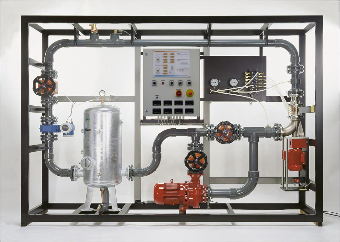
The core piece of the experimental plant is the Sci-tech Axial Turbo-machines Model FM 87 with attached motor/generator. It can be operated either as a pump or turbine. To this end, different sets of paddles are used.
The transparent housing allows a full view of the blades and flow processes. A compressed-air powered equalization basin can quickly flood the system. Operation under different pressure levels is possible in order to study the cavitation. The braking power is fed back into the grid.
A water tank allows the turbo-machine to be converted without loss of water. In turbine mode the turbo-machine is driven by means of a powerful pump. The extra rotors and stators supplied with different blade angles allow sophisticated experiments. Velocity triangles can be used for the graphical representation of the velocity conditions at the water inlet and outlet as well as within the turbo-machine.
The speed is detected contact-free by means of an inductive displacement sensor on the motor shaft. To determine the drive power, the drive motor is mounted on swivel bearings and equipped with a force sensor to measure the drive torque. The differential pressure is detected radially in different blade planes by means of a 3-hole probe. Manometers measure the inlet and outlet pressures. The flow rate is measured by an electromagnetic flow meter. The measured values are read from digital displays.
The experimental plant contains a closed water circuit with tank and centrifugal pump.
The well-structured instructional material sets out the fundamentals and provides a step-by-step guide through the experiments.
| Size: | 240cm x 120cm x 260cm (LxWxH) |
| Weight: | 235 kg |
Item Description
Features
* Investigation of a single-stage axial turbo-machine 1
* Can be operated as pump or turbine by changing the paddels1
* Transparent working area
The core piece of the experimental plant is the Sci-tech Axial Turbo-machines Model FM 87 with attached motor/generator. It can be operated either as a pump or turbine. To this end, different sets of paddles are used.
The transparent housing allows a full view of the blades and flow processes. A compressed-air powered equalization basin can quickly flood the system. Operation under different pressure levels is possible in order to study the cavitation. The braking power is fed back into the grid.
A water tank allows the turbo-machine to be converted without loss of water. In turbine mode the turbo-machine is driven by means of a powerful pump. The extra rotors and stators supplied with different blade angles allow sophisticated experiments. Velocity triangles can be used for the graphical representation of the velocity conditions at the water inlet and outlet as well as within the turbo-machine.
The speed is detected contact-free by means of an inductive displacement sensor on the motor shaft. To determine the drive power, the drive motor is mounted on swivel bearings and equipped with a force sensor to measure the drive torque. The differential pressure is detected radially in different blade planes by means of a 3-hole probe. Manometers measure the inlet and outlet pressures. The flow rate is measured by an electromagnetic flow meter. The measured values are read from digital displays.
The experimental plant contains a closed water circuit with tank and centrifugal pump.
The well-structured instructional material sets out the fundamentals and provides a step-by-step guide through the experiments.
Technical Specifications
Specifications
- Investigation on an axial flow turbomachine
- Closed water circuit with tank and centrifugal pump
- Turbomachine may be operated as a turbine and as a pump
- Two sets of paddles for pump mode and two sets of paddles for turbine mode with different entry and exit angles.
- Asynchronous motor/generator with 4-quadrant operation via frequency converter
- Regenerative feedback of the brake energy
- Motor with pendulum bearing torque measurement via lever arm and force sensor
- Inductive speed sensor on the motor
- Manometer for measuring the inlet and outlet pressures.
- Measuring probe and differential pressure sensor for recording the pressure curve in the turbomachine
- Electromagnetic flow meter
- Display of power consumption, torque, speed, pressure, differential pressure and flow rate
Technical Specifications
Centrifugal pump
– power: 5,5kW
– max. flow rate: 150m³/h
– max. head: 10m
Motor/generator
– power: 1,5kW
– torque: 0…5Nm
– speed: 0…3000min-1
Water tank: 150L
Measuring ranges
– pressure (manometer): 2x -1…5bar
– differential pressure: 5x 0…500mbar
– flow rate: 0…150m³/h
– speed: 0…9999min-1
– torque: 0…5Nm
Experiments
- Recording characteristic curves
- Determining dimensionless characteristics
- Velocity triangles and pressure curves
- Investigation of energy conversion within the turbomachine
- How blade shape affects power and efficiency
- Determine the outlet angular momentum and its effect on the power.
- Cavitation effects
Services Required
- Mains power supply: 220-240V, 1Ph, 50Hz
- Compressed air connection: 3…10bar
Model Number
FM 87
See also different:

Sci-tech 20kN Tensile, Compression & Brinell Mechanical Tests Set up Model MT 088 covers tensile tests, compression tests and Brinell hardness tests in the base unit. Bending, shear and cupping tests can be conducted using the accessories. [...]


