Torsion of Bars Apparatus Model MT 038
Home » Products » Torsion of Bars Apparatus Model MT 038
Torsion of Bars Apparatus Model MT 038
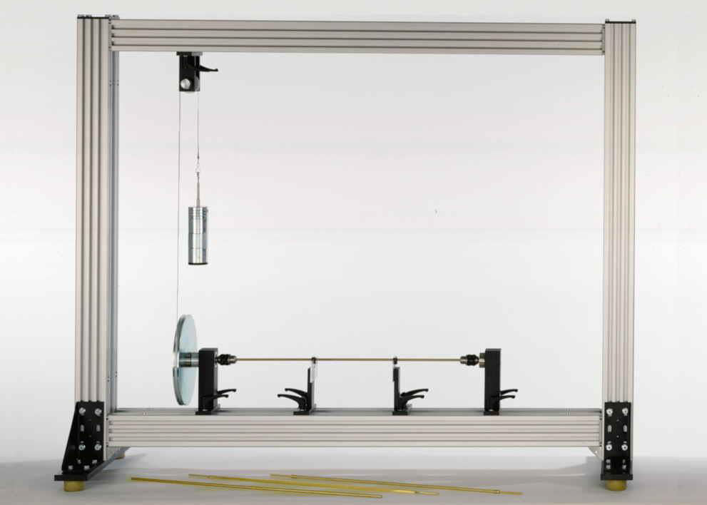
Sci-tech Torsion of Bars Apparatus Model MT 038 investigates the torsion of a bar under a torque. The bar is clamped into two movable bearing blocks by a chuck. The torque is generated by a circular disc, a deflection roller and a weight. The clamping length and torque can be varied. The resultant torsion is read-off at two random points on the bar by means of angle indicators.
The fundamentals of elastic torsion are illustrated by the round bar. Three other bars are provided in order to investigate special cases: two thin-walled enclosed sections (a tube and a square tube) and a longitudinally slotted tube (thin-walled open section).
| Size: | 110cm x 40cm x 90cm (LxWxH) |
| Weight: | 15 kg |
Item Description
Features
* Elastic torsion of a bar1
* Round bar, tube, longitudinally slotted tube and square tube as test bars1
* Indication of the angle of twist at two random points on the bar
Torsion occurs primarily on axles and drive shafts in motor vehicles and machines. The torsion occurring in the shaft cause cross-sections of the shaft to be pushed together around the longitudinal axis. When a torque is applied to a circular shaft the cross-section remains flat and no warpage occurs.
In the event of minor torsion the length and radius remain unchanged. The straight lines on the outer circumference of the shaft running parallel to the axis become helixes. Non-circular cross-sections mostly result in warpage.
Sci-tech Torsion of Bars Apparatus Model MT 038 investigates the torsion of a bar under a torque. The bar is clamped into two movable bearing blocks by a chuck. The torque is generated by a circular disc, a deflection roller and a weight. The clamping length and torque can be varied. The resultant torsion is read-off at two random points on the bar by means of angle indicators.
The fundamentals of elastic torsion are illustrated by the round bar. Three other bars are provided in order to investigate special cases: two thin-walled enclosed sections (a tube and a square tube) and a longitudinally slotted tube (thin-walled open section).
All the component elements of the experiment are clearly laid-out and housed securely in a storage system. The complete experimental set-up is arranged in the frame.
The well-structured instructional material sets out the fundamentals and provides a step-by-step guide through the experiments.
Technical Specifications
Specifications
Bench-top unit with adjustable legs.
Anodized aluminum frame and panels in painted steel.
The apparatus mainly consists of:
– Main frame that is supported on two aluminum blocks. It consists of two guides made of stainless steel. The rest of the components are made of aluminum.
– Two guides of the unit on which the mobile clamp slides are for testing rods of different lengths.
– Mobile clamp located at one end that has a crank in the bottom to adjust the test rod to the desired length. It is made of stainless steel.
– Fixed clamp, consists of two bearings which allow it to turn. It has an arm on which the force is applied. It has a notch placed 60 mm from the longitudinal axis of the test rod, to carry out the measurements. The dial gauge should be placed on this notch to properly measure the deformation. The clamp is made of stainless steel.
– Test rods: standard supply of 3 test rods made of steel, brass and aluminum. They are 8 mm in diameter and 350 mm in length. They have marks every 50 mm, to make the performance of practical exercises at different lengths easier.
– A Dynamometer up to 10 Kg, with a 50 g accuracy, to apply the forces on the test rod.
– A Dial gauge of 0- 10 mm, with 0.01 mm accuracy, to measure the deformation of the test rod subjected to the force.
All the necessary tools to carry out the experiments are provided. One Allen key is supplied to adjust the dial gauge and one Allen key is supplied to tighten the clamps
Elastic torsion of bars
Two movable bearing blocks with clamping chuck for mounting of bars, 1 fixed and 1 movable bearing
Two movable angle indicators can be clamped to the bar
Four bars: round bar with full cross-section, tube, longitudinally slotted tube, square tube
Application of load to the bar by a mass disc, a deflection roller and a set of weights.
Optional electronically driven motorized drive & ‘Sci-Cal’ DAQ interface
Technical Specifications
4 brass bars, length 695mm
– round bar, diameter 6mm
– tube, slotted tube
d=6mm, wall thickness: 1mm, slot width: 0,3mm
– square tube
WxH: 6mm, wall thickness: 1mm
Disc to apply the load
– effective radius: 110mm
Angle indicator
– measuring range: -90°…+90°, graduations: 1°
- (Optional Geniometer available)
Weights
– 1x 1N (hanger)
– 4x 1N
– 3x 5N
Experiments
– torsion of a bar
– shear modulus of elasticity and 2nd polar moment of area
– angle of twist dependent on clamping length
– angle of twist dependent on torque
– influence of rigidity on torsion
* round bar with full cross-section
* tube
* tube, longitudinally slotted
* square tube
– calculation of angle of twist
– comparison of calculated and measured angle of twist
Scope of Delivery
2 bearing blocks with clamping chuck
2 angle indicators
4 bars
1 deflection roller with fixture
1 cable
1 set of weights
2 hexagon socket wrenches
1 storage system with foam inlay
1 set of instructional material
Model Number
MT 038
See also different:

A) HARTLY, COLPITTS, CLAPP, BLOCKING OSCILLATORS Model ETR027/1 B) CRYSTAL OSCILLATOR, ASTABLE, MONOSTABLE & BISTABLE MULTIVIBRATOR Model ETR 027/2 C) PHASE SHIFT OSCILLATOR USING FET, JFET OSCILLATOR CHARACTERISTICS OF JFET Model ETR 027/ [...]


