Gas Flow Classification Model TH 124
Home » Products » Gas Flow Classification Model TH 124
Gas Flow Classification Model TH 124
– Gas flow classification with a zigzag sifter
– Transparent duct to observe the separation process
– Practical experiments on a laboratory scale
Item Description
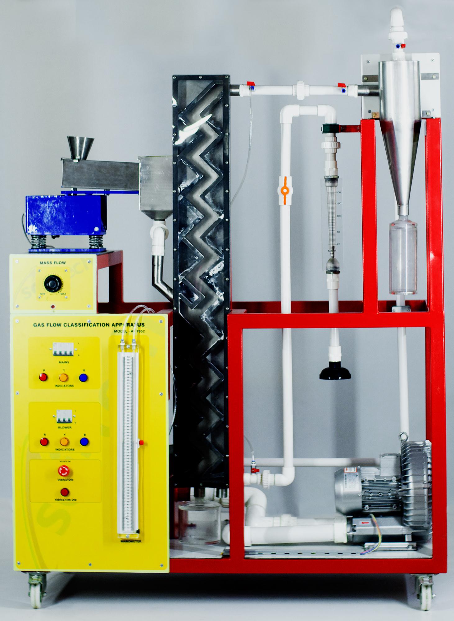
Zigzag sifters permit classification of solid compounds. The solid compound being separated is charged into the feed hopper. The compound is fed into the zigzag duct of the sifter at mid-height by way of a vibrating trough. An air flow flows upwards through the vertical duct. Depending on the geometry and density of the particles, they are carried along by the air or drop down due to gravity. At every bend in the duct the solid compound passes through the air flow and falls onto the opposite wall of the sifter. This corresponds to one sifting stage. Owing to the flow conditions, a vortex wake is formed between two bends of the zigzag duct. It ensures that the solid matter moves roughly perpendicular to the air flow. In this way, a transverse sift takes place at every bend. Sequencing of large numbers of such stages results in very fine separation. Sci-tech Gas Flow Classification Model TH 124 features a 20-stage zigzag duct. Transparent material provides optimum observation of the processes in the duct.
A fan generates the air flow. The volumetric air flow rate and the solid mass flow are adjustable. The fine material transported upwards with the air flow is separated by a cyclone. Pressure measurement points at the relevant positions in the trainer enable the pressure loss to be determined.
Activated carbon in different particle sizes is recommended for use as the feed material. For particle size analyses of the feed and of the coarse and fine material, a balance and a screening machine TH 125 are recommended.
Technical Specifications
1. Zigzag sifter to separate solid compounds
2. Feed hopper with vibrating trough for feed of solid compound into sifter
3. Dosage of feed material by way of distance of hopper outlet from vibrating trough and frequency of vibrating trough
4. Separation of solid compound into coarse and fine material with air flow in 20-stage zigzag duct
5. Air flow generation by fan; adjustment by valve
6. Separation of fine material from air flow by gas cyclone with tangential inlet
7. 3 tanks for feed material and coarse and fine materials 8. Recording of volumetric air flow rate and differential pressure through sifter and cyclone.
Technical Specifications
Vibrating trough
– mass flow: max. 10kg/h
– vibration frequency: max. 3000min-1
Zigzag sifter
– height: approx. 1500mm
– cross-sectional area: 40x50mm
Cyclone
– height: approx. 550mm
– diameter: 150mm
Fan
– volumetric flow rate: max. 600m3/h
– power consumption: approx. 3600W
Tanks
– feed hopper: 3L
– coarse material: 2L
– fine material: 2L
Measuring ranges
– cyclone and sifter differential pressures: 0…100mbar
– volumetric flow rate (air): approx. 10…100m3/h
See also different:

Sci-tech Axial Flow Impulse Turbine Test Apparatus Model FM 35 consists of an inlet manifold which supplies water to four jets which are equally spaced around the turbine runner. Each of the jets can be individually controlled using ball valve [...]


