Open Wind Tunnel - Subsonic Model AT 002
Home » Products » Open Wind Tunnel – Subsonic Model AT 002
Open Wind Tunnel – Subsonic Model AT 002
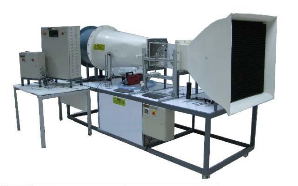
Sci-tech Open Wind Tunnel – Subsonic Model AT 002 setup is an open wind tunnel used to demonstrate and measure the aerodynamic properties of various models. For this purpose, air is drawn in from the environment and accelerated. The air flows around a model, such as an aero foil, in a measuring section. The air is then decelerated in a diffuser and pumped back into the open by a fan.
The carefully designed nozzle and a flow straightener ensure a uniform velocity distribution with little turbulence in the closed measuring section. The flow cross section of the measuring section is square. The built-in axial fan and a variable-speed drive is characterized by an energy-efficient operation at high efficiency. Air velocities of up to 30 m/s can be reached in this open wind tunnel. The air velocity in the measuring section is displayed on the inclined tube manometer.
Extensive accessories allow a variety of experiments, for example lift measurements, pressure distributions, boundary layer analysis.
Size: | 350cm x 80cm x 85cm (LxWxH) |
Weight: | 230 kg |
Item Description
Features
- Open wind tunnel for a variety of aerodynamic experiments
- Homogeneous flow through the flow straightener and special nozzle section
- Transparent test section
- Experiments from the field of aerodynamics and fluid mechanics with an “Eiffel” type wind tunnel
- Wide range of accessories available
- Transparent, closed measuring section
- Inlet contour, nozzle and diffuser made of FRP
- Variable‐speed fan motor for energy‐efficient operation
- Flow straightener reduces turbulence
- Electronic two‐component force sensor for measuring the flow forces
- Inclined tube manometer for displaying the air velocity
- Digital display of drag and lift
- Comprehensive selection of optional instrumentation, models and accessories.
- High Speed Data Acquisition System for computer control of wind tunnel & measurement of parameters like Pressure distribution, Lift & Drag Forces, Velocity & Angle of attack.
Sci-tech Open Wind Tunnel – Subsonic Model AT 002 setup is an open wind tunnel used to demonstrate and measure the aerodynamic properties of various models. For this purpose, air is drawn in from the environment and accelerated. The air flows around a model, such as an aero foil, in a measuring section. The air is then decelerated in a diffuser and pumped back into the open by a fan.
The carefully designed nozzle and a flow straightener ensure a uniform velocity distribution with little turbulence in the closed measuring section. The flow cross section of the measuring section is square. The built-in axial fan and a variable-speed drive is characterized by an energy-efficient operation at high efficiency. Air velocities of up to 30 m/s can be reached in this open wind tunnel. The air velocity in the measuring section is displayed on the inclined tube manometer.
Extensive accessories allow a variety of experiments, for example lift measurements, pressure distributions, boundary layer analysis.
Optional data acquisition system has been developed specifically to support the analysis of experiments with the wind tunnel. Data Acquisition System consists of an interface module for sensors used with Subsonic Wind Tunnel. The system supports experiments such as measurement of lift and drag on drag bodies, pressure distribution on an aero foil or a cylinder. Therefore, depending on the experiments, pressure sensors, angle sensors and the electronic displacement measurement and the three-component force sensor can be connected to the interface module.
Velocity, pressure, angle of attack or displacement and lift and drag forces are transmitted via USB directly to an integrated PC where they can be analyzed using the ‘Sci-Cal’ software.
Technical Specifications
Specifications
- Compact, free-standing open-circuit suction subsonic wind tunnel with a working section of 300~310 mm by 300~310 mm and 600~620 mm long
- Air velocity: 0 to 36 m/s
- Air enter the tunnel through an aerodynamically designed effuser (cone) that accelerates the air linearly
- It then enters the working section and pass through a grille before moving through a diffuser and then to a variable speed axial fan
- The grille protects the fan from damage by loose objects
The air leaves the fan, pass through a silencer unit and then back out to the atmosphere
- A separate control and instrumentation unit controls the speed of the axial fan (and the air velocity in the working section)
- The control and instrumentation unit includes manometers and electrical outlets to supply electrical power to other instruments.
- A metal frame supports the wind tunnel
- The frame includes lockable castors for convenient mobility
- The working section of the tunnel is a square section with a clear roof, sides and floor
- The sides are removable and the floor and each side panel have a special position to support the wind tunnel models
- Supplied with the wind tunnel are a protractor and a model holder to support and accurately adjust the angle of models fitted
- Two traversing probes are fitted on the working section
- One is a Pitot-static tube and the other is a standard Pitot tube
- They fit upstream and downstream of the models and connect to the manometers on the instrumentation unit to show pressure
- The model holder supplied to hold a model
- It is designed to hold a shaft of diameter 11.95 ±0.015 mm (diameter) and 215 ±1.25 mm (length) mounting stem
- The protractor fits on to the shaft of a model when a Balance is not being used
- It can be used when setting up models and rotating them during experiments
Three Component Balance Module AT002/01:
- The Three-Component Balance fits onto the working section of the above Subsonic Wind Tunnel
- Provides an easy-to-use support system for wind tunnel models
- It measures lift, drag and pitching moment exerted on the model
- The balance comprises a mounting plate secured to the wind tunnel working section
- A triangular force plate is held on the mounting plate by a mechanism that constrains it to move in a plane parallel to the mounting plate only, while leaving it free to rotate about a horizontal axis
- This arrangement provides the necessary three degrees of freedom
- The forces acting on the model are transmitted by cables to three strain gauged load cells
- The output from each load cell is taken via an amplifier to a display module
- The display module is mounted onto the wind tunnel control and instrumentation frame and includes a digital display to show the lift, drag and pitching moment directly
- The equipment should be fully compatible with ‘Sci-Cal’ Data Acquisition System and can quickly and conveniently connect to the frame-mounted interface unit
- The model support of the balance can be rotated by 360 degrees
- This allows adjustment of the angle of incidence of the model to the direction of air flow
- The model support can be locked in the required position by a simple clamp after adjustment
Balance Angle Feedback Unit Module AT002/02:
- The Balance Angle Feedback Unit to be used with the Three- Component Balance to measure the angular position of models mounted on the balance in the wind tunnel
- Mountable on the Three-Component Balance attached to the wind tunnel
- Transmits the rotational angle of the model to data acquisition system
- The angle of the model can be logged on a suitable computer along with the other captured experimental data
Differential Pressure Unit (2 Nos.) Module AT002/03:
- The Differential Pressure Transducer and readout measures and display pressures in Pitot-static tubes and other pressure-sensing devices fitted to a wind tunnel, with respect to the atmosphere or differential pressures
- The control and instrumentation panel includes a location for mounting up to two Differential Pressure Transducer modules
- Each module contains a calibrated pressure transducer
- The unit has an integral liquid crystal display that allows the user to read pressure directly
- The signals of the pressure sensors can be output to Data Acquisition System
- When the Differential Pressure Transducer is used with the automatic data acquisition unit provides a significant advantage over conventional instruments such as manometers.
16 to 32-Way Pressure Display Unit Module AT002/04 (to be advised):
- The 16 to 32-Way Pressure Display Unit measures and display up to 16 to 32 different pressures from models and other measuring instruments fitted to a wind tunnel
- It ideally suites in applications where multiple pressure measurements are required, for example in tapped aerofoil model investigations
- The unit is mounted onto the control and instrumentation frame of the wind tunnel
- The unit contains between 16 to 32 calibrated pressure transducers
- Input connection to each are via quick-release pressure inputs mounted on the front panel of the unit
- This allows easy and quick connection between the unit and an experiment mounted in a wind tunnel
- All pressures are measurable with respect to atmosphere
- The unit has an integral liquid crystal display with a scroll switch that allows all channels to be viewed in groups of four at any time
- The conditioned outputs of the pressure sensors can be output to ‘Sci-Cal’ Data Acquisition System
- When the 16 to 32- Way Pressure Display Unit is used with the system it allows laboratory time to be used more efficiently because data can be captured and processed much more quickly than when using manual techniques
- The facility in the software to average data to remove the fluctuations inherent in wind tunnel measurements, enhances the quality of the results by making their interpretation much easier
Pitot Static Traverse Module AT002/05:
- A Pitot-static tube that is mounted in the working section of the wind tunnel, either upstream of the position of the test model or on the fore-aft traverse
- This allows students to do ‘wake’ traverses, of a model
- The vertical position of the tube, which is adjustable, displays on a digital indicator
- The digital indicator position can be set to zero in any position
- The position of the Pitot-static Traverse to be output to data acquisition system unit to allows computer-based data acquisition and display
Technical Specifications
- Dimensions (Assembled): L x W x H: 3 m x 1 m x1.2 m
- Working section: 300 mm x 300 mm, and 600 mm long, Made in Plexi-glass
- Air velocity: 0 to 36 m/s
- Fan:
- Type: Axial Fan,
- Rated Air Flow: Upto 11,000 m3/hr
- Fan Motor:
- Capacity 3 hp,
- Speed: 1440 / 2800 RPM
- Make: Siemens / ABB
- Variable Speed Drive:
- Type: Micro-processor Based VFD
- Capacity 3 hp
- Supply Voltage: 380 – 440 V AC, Three Phase
- Make: Delta / ABB
- Air Flow Measurement by Pitot Tube & Manometer
- 16 Tube, Inclined Manometer (AF-02.01)
- Three Component Force Balance for Lift, Drag & Pitch Measurement with digital indicator
- Cylinder model for pressure measurement
- NACA 2412 Aerofoil for Drag Measurement
- NACA 0012 Aerofoil with Pressure Tappings
- Three Dimensional Drag Models
- 12 Chanel Electronic Manometer Bank
- Measures up to 12 different pressures from models
- All pressures are measured with respect to atmosphere
- Range 0-300 mm of H2O
- Angle Feedback Unit
- Pitot Traverse Mechanism
- Data Acquisition System and Software:
- USB Based Multi-Functional Data Acquisition Device
- 16 to 32 Analog inputs (16-bit, 250 kS/s)
- 2 Analog outputs (16-bit, 250 kS/s);
- 4 digital I/O
- Make: National Instruments, USA
- Lab view based customized programmed software and Data processing:
LabVIEW based software with Graphical & Numerical displays for parameters measured by
different sensors.
The software enables user to control the air speed from computer.
Following measured parameters are displayed on screen during experimentation –
- Air Velocity
- Pressure Distribution around different models
- Lift & Drag Forces
- Angle of Attack
- The software analyses experimental data & performs calculations.
- Experimental test results are displayed in tabular format along with relevant graphs.
- The measured parameters, test results can be exported in to Excel format or Printed using any printer connected to computer / laptop.
Experiments
- Flow past bodies with pressure and velocity observations in the wake
- Performance of an aerofoil
- Pressure distribution around a cylinder
- Study of the characteristics of models involving basic measurement of lift and drag forces
- Study of the pressure distribution around an aerofoil model to derive the lift and comparison with direct measurement of lift
- Drag force on a body normal to an air flow
- Determine drag and lift coefficients for different models (Aerofoil and Flat plate)
Optional Accessories
- Data Acquisition System
- Three-Component Balance
- Angle Feedback Unit
- 16 Way Digital Pressure Display Unit
- Smoke Generator
Model Number
AT 002