Unsymmetrical Bending & Shear Centre Apparatus Model MT 067
Home » Products » Unsymmetrical Bending & Shear Centre Apparatus Model MT 067
Unsymmetrical Bending & Shear Centre Apparatus Model MT 067
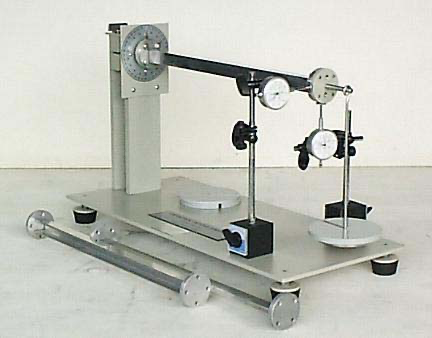
Experiment investigating with the Sci-tech Unsymmetrical Bending and Shear Centre Apparatus Model MT 067, of different sectioned beams when the loading is not in the plane of a principal axis. A ‘U’ section, ‘L’ section and rectangular beam cantilever is horizontally supported within a rotating clamp which fits in a substantial frame attached to the Universal Frame and Stand. The rotating clamp enables the loading and deflection planes to be set relative to the cross-section axes. A protractor scale is fitted to the substantial block and a pointer on the specimen references against this scale.
At the other end of the cantilever specimens is a boss onto which two dial gauges rest and through which the vertical loading is applied. The flat anvils of the dial gauges ensure a consistent flat surface during cantilever deflection. The dial gauges are mounted at right angles to each other and have full positional adjustment available. For shear centre work, additional loading bars are supplied that attach into the free end of the specimens, onto which the dial gauges can be referenced. Loading is applied to the specimens using a load hanger and calibrated weights set.
| Size: | 80cm x 70cm x 70cm (LxWxH) |
| Weight: | 20 kg |
Item Description
Experiment investigating with the Sci-tech Unsymmetrical Bending and Shear Centre Apparatus Model MT 067, of different sectioned beams when the loading is not in the plane of a principal axis. A ‘U’ section, ‘L’ section and rectangular beam cantilever is horizontally supported within a rotating clamp which fits in a substantial frame attached to the Universal Frame and Stand. The rotating clamp enables the loading and deflection planes to be set relative to the cross-section axes. A protractor scale is fitted to the substantial block and a pointer on the specimen references against this scale.
At the other end of the cantilever specimens is a boss onto which two dial gauges rest and through which the vertical loading is applied. The flat anvils of the dial gauges ensure a consistent flat surface during cantilever deflection. The dial gauges are mounted at right angles to each other and have full positional adjustment available. For shear centre work, additional loading bars are supplied that attach into the free end of the specimens, onto which the dial gauges can be referenced. Loading is applied to the specimens using a load hanger and calibrated weights set.
A comprehensive instruction manual for lecturer and student, giving full details on apparatus assembly and operation as well as example results. All necessary assembly and operational tools are provided.
See also different:

Sci-tech Geneva Mechanism Model MT 113 has been designed to demonstrate the action of a Geneva drive during the indexing and rest periods. Sci-tech Geneva Drive Mechanism Model MT 113 is a mechanism that transforms continuous circular motion i [...]


