20M ADJUSTABLE BED FLOW CHANNEL UNIT Model FM 3210~20M

The Sci-tech 20M Adjustable Bed Flow Channel Unit Model FM 32 10M~20M is suitable for demonstrations and teaching of open channel flows. By closing the top of the channel, the unit can also be used to demonstrate duct flows. The complete unit is mounted on a mobile platform fixed on castor wheels. The apparatus is self sufficient with water recirculation system consisting of flow inlet tank, centrifugal pump, flow control valves, discharge tank, water flow meter and sump tank. The inlet tank consists of baffle plate and screens to reduce disturbances in the flow. The discharge tank consists of adjustable over flow weir which can be adjusted to control flow conditions in the working section. The working section is transparent and is made of clear acrylic. Other components of the unit are made of corrosion resistant materials. Experiments can be conducted in both open channel flow and duct flow modes. The channel consists of adjustable floor section which along with the transition section can be raised or lowered using suitable inserts. The combination of adjustable floor and upper boundary plate enable formation of various types of ducts to conduct experiments. Flow control valve is provided upstream of the inlet tank control flow rate. The mid-section of the upper boundary wall is made removable for fast changing and installation of models in the working section. Total pressure probes and static pressure tapings are provided at five locations along the working section. Total pressure probes can be moved vertically and fixed at different positions over the depth of the channel. Different models, such as hump, weirs etc., required to carry out studies mentioned in the list of experiments are supplied. Provision is made to fix models in the working section using suitable fixtures.

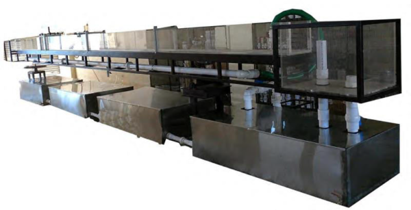
Size: 1200~2400cm x 300~1000cm x 600~1000cm (LxWxH)
Weight: 350 kg

Item Description

Study of open channel flows is a subject of interest in basic fluid mechanics and Hydraulics. A flow channel with a provision to control depth of flow over in the channel can provide a very useful tool to study several aspects of open channel flows. Adjustable Bed Flow Channel Unit is an essential equipment for fluid mechanics, hydraulics, civil, mechanical and related laboratories in science and engineering institutions.  

The Sci-tech 20M Adjustable Bed Flow Channel Unit Model FM 32 10~20M is suitable for demonstrations and teaching of open channel flows. By closing the top of the channel, the unit can also be used to demonstrate duct flows. The complete unit is mounted on a mobile platform fixed on castor wheels. The apparatus is self sufficient with water recirculation system consisting of flow inlet tank, centrifugal pump, flow control valves, discharge tank, water flow meter and sump tank. The inlet tank consists of baffle plate and screens to reduce disturbances in the flow. The discharge tank consists of adjustable over flow weir which can be adjusted to control flow conditions in the working

section. The working section is transparent and is made of clear acrylic. Other components of the unit are made of corrosion resistant materials. Experiments can be conducted in both open channel flow and duct flow modes. The channel consists of adjustable floor section which along with the transition section can be raised or lowered using

suitable inserts. The combination of adjustable floor and upper boundary plate enable formation of various types of ducts to conduct experiments. Flow control valve is provided upstream of the inlet tank control flow rate. The mid-section of the upper boundary wall is made removable for fast changing and installation of models in the working section. Total pressure probes and static pressure tapings are provided at five locations along the working section. Total pressure probes can be moved vertically and fixed at different positions over the depth of the channel. Different models, such as hump, weirs etc., required to carryout studies mentioned in the list of experiments are supplied. Provision is made to fix models in the working section using suitable fixtures.  
Technical Specifications

 Specifications for Channel Flume:

  1. Open channel flow and duct flow modes of operation.
  2. Self contained unit consisting of diaphragm flow control valve, inlet tank with baffle plate and screens, centrifugal pump, flow meter, discharge tank with adjustable over flow weir and sump tank.
  3. Working section, metal channel frame with clear acrylic/glass sides, length: 10m to 20m, width: 100mm, height: 300mm.
  4. Transition section and adjustable floor section.
  5. Floor inserts for converging and converging-diverging duct flows.
  6. Upper boundary plate.
  7. Weirs (3 Nos).
  8. Models: hump, sluice gate.
  9. Model fixtures.
  10. Total pressure probes (3 Nos) with fixtures to vary position.
  11. Static pressure taps (3 Nos).
  12. Max. free surface depth: 250mm
  13. Max. bed height above channel: 220mm.
  14. Max. pump flow: 5.liters/sec

Options:

  1. Flow visualisation system consisting of dye injection tank of 0.5 liters reservoir capacity, 5 Nos. dye injection needles with needle valves at exit can be supplied on request.
  2. Software with interface & required sensors for signals & readings to be tabulated in DAQ software

Sci-tech ‘Sci-Cal’ Automated operation and data acquisition: the experimental flume FM 32 can be operated by a PC. Flow rate, inclination adjustment and frequency of the wave generator can be set by Sci-tech ‘Sci-Cal’ software. Measured values can be recorded and saved. The software detects automatically if the electronic pressure measurement is also used. In this case, both softwares are operated in FM 32 including the selection of the corresponding windows. FM 32, can optionally include a control with PLC via two touch panels and ‘Sci-Cal’ software for acquisition of the measured values. (‘Sci-Cal’ Software must be purchased at the time of order because it cannot be retrofit)

  1. Wave Maker with optional software
  2. Artificial beach with slope
  3. Any other models required by the user can be supplied on request.

Services Required:

  1. Water Supply.
  2. Electrical Supply, 240/440V,3Ph, 50 Hz.


ADDITIONS & ACCESSORIES TO ‘Adjustable Bed Flow Channel’:

  1. Extension Element of the ‘Adjustable Bed Flow Channel’ Model FM32A
  2. Extension Water Sump Tank of the ‘Adjustable Bed Flow Channel’ Model Model 32B
  3. Sluice Gate for the ‘Adjustable Bed Flow Channel’  Model 32C
  4. Radial Gate for the ‘Adjustable Bed Flow Channel’ Model 32D
  5. Set of Weir Plates for the ‘Adjustable  Bed Flow Channel’ Model 32E
  6. Broad Crested Weir for the ‘Adjustable Bed Flow Channel’ Model 32F
  7. Crump Weir for the ‘Adjustable Bed Flow Channel’ Model 32G
  8. Siphon Weir for the ‘Adjustable Bed Flow Channel’ Model 32H
  9. Rake for the ‘Adjustable Bed Flow Channel’ Model 32I
  10. Ogee-Crested Weir with Pressure Measurement for the ‘Adjustable Bed Flow Channel’ Model 32J
  11. Ogee-Crested Weir with 2 weir Outlets for the ‘Adjustable Bed Flow Channel’ Model 32K
  12. Venturi Flume for the ‘Adjustable Bed Flow Channel’ Model 32L
  13. Pitot static Tube for the ‘Adjustable Bed Flow Channel’ Model 32M
  14. Velocity Meter for the ‘Adjustable Bed Flow Channel’ Model 32N
  15. Instrument carrier for the ‘Adjustable Bed Flow Channel’ Model 32O
  16. 10 Tube Manometer for the  ‘Adjustable Bed Flow Channel’ Model 32P
  17. Parshall Flume for the ‘Adjustable Bed Flow Channel’ Model 32Q
  18. Cut Throat Flume for the ‘Adjustable Bed Flow Channel’ Model 32R
  19. Culvert for the ‘Adjustable Bed Flow Channel’ Model 32S
  20. Culverts – Gutters Model 32SG
  21. Wave Generator for the ‘Adjustable Bed Flow Channel’ Model 32T
  22. Plain Beach for the ‘Adjustable Bed Flow Channel’ Model FM32U
  23. Set of Piers & Profiles Model FM 32 V
  24. Bridge piers Model FM 32 VBP
  25. Vortex Induced Vibrations Model F32VVV
  26. Rectangular and V-Notch Weirs for the ‘Adjustable Bed Flow Channel’ Model FM32 W
  27. Roughened Gravel Bed for the ‘Adjustable Bed Flow Channel’ Model FM32 RB
  28. Roughened Sand Bed for the ‘Adjustable Bed Flow Channel’ Model FM32 RBS
  29. Roughened Turf Bed for the ‘Adjustable Bed Flow Channel’ Model FM32 RBT
  30. Lift and Drag module FM 32X

  31. Trapezoidal 45º WSC Basket Model FM32Y

  32. Large 60º V Trapezoidal flume Model FM 32Z
  33. Palmer Bowlus Flume Model FM32AA
  34. Sediment Loop Model FM32BB
  35. Static Pressure Scanner & Display Model FM 32CC
  36. PIV laser system for measurement and visualization of flows Model FM32DD


List of Experiments:

  1. Demonstration of open channel flows.
  2. Demonstration of duct flows.
  3. Demonstration of Bernoulli’s equation in converging flows.
  4. Energy losses in converging and diverging flows.
  5. Study of flow over weirs.
  6. Specific energy relationships for sub-critical and super-critical flows.
  7. Critical depth – upstream water level studies.
  8. Flow over broad crested weirs.
  9. Flow under sluice gate.
  10. Study of hydraulic jump.
  11. Surface wave studies.
  12. Characteristics of flow over rectangular thin plate weirs (Overshot)
  13. Characteristics of flow over profiled thin plate weirs (Overshot)
  14. Characteristics of flow over a sharp cornered broad crested weir
  15. Characteristics of flow over a streamlined broad crested weir
  16. Characteristics of flow over a Crump Weir
  17. Characteristics of flow over an Ogee Weir
  18. Characteristics of flow through a Venturi flume
  19. Characteristics of flow through a Parshall Flume
  20. Characteristics of flow through a WSC Flume
  21. Characteristics of flow over a Sill
  22. Characteristics of flow over a Dam Spillway
  23. Characteristics of flow over a Siphon Spillway
  24. Characteristics of flow through a self-regulating siphon
  25. Characteristics of Flow over a Gravel Bed
  26. Characteristics of flow over a Corrugated Bed
  27. Characteristics of flow around a Cylindrical Pile
  28. Characteristics of flow through a Culvert
  29. Characteristics of flow under a Radial Gate
  30. Critical depth– Derivation of the Specific Energy Equation
  31. Discharge beneath a Sluice Gate (Undershot weir)
  32. Force on a Sluice Gate (Undershot weir)
  33. The Lift and Drag Force on Submerged Structures
  34. Observation of scour at Pier legs
  35. Head loss through a Trash Rack
  36. Flow visualisation and study of stream line patterns. (OPTIONAL)
  37. Demonstration of laminar and turbulent flow by flow visualisation. (OPTIONAL)

Model Number

FM 32 10M~20M