Pressure Loss in Pipes Apparatus MODEL FM 07
Home » Products » Pressure Loss in Pipes Apparatus MODEL FM 07
Pressure Loss in Pipes Apparatus MODEL FM 07
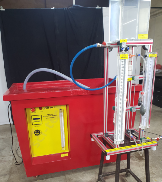
Sci-tech Pressure Loss in a Pipe Apparatus Model FM 07 has been designed to enable students to measure loss of head due to friction in a pipe and to study the effect of change in flow velocity. Laminar and turbulent flow regimes can be obtained by varying the flow velocity and hence the flow Reynolds number. The apparatus consists of a horizontal test pipe with static pressure tapings at the upstream and downstream ends to measure head loss due to friction. Extra pipe lengths are provided at the inlet and exit to allow the flow to become fully developed and to damp out the flow disturbance originating from the valves and fittings. The test pipe is mounted on a support frame and there is a provision for levelling. Water is supplied from the hydraulic bench (for higher flow rates) and the constant head feeding tank (for lower flow rates).
| Size: | 30cm x 30cm x 80cm (LxWxH) |
| Weight: | 25 kg |
Item Description
Study of pressure loss in pipes is important in view of the loss of head due to friction and consequent pumping power requirements in any pipe system. Sci-tech Pressure Loss in a Pipe Apparatus Model FM 07 is an experimental set-up necessary for any Fluid Mechanics and Hydraulics Laboratory of an educational institution.
Sci-tech Pressure Loss in a Pipe Apparatus Model FM 07 has been designed to enable students to measure loss of head due to friction in a pipe and to study the effect of change in flow velocity. Laminar and turbulent flow regimes can be obtained by varying the flow velocity and hence the flow Reynolds number. The apparatus consists of a horizontal test pipe with static pressure tapings at the upstream and downstream ends to measure head loss due to friction. Extra pipe lengths are provided at the inlet and exit to allow the flow to become fully developed and to damp out the flow disturbance originating from the valves and fittings. The test pipe is mounted on a support frame and there is a provision for levelling. Water is supplied from the hydraulic bench (for higher flow rates) and the constant head feeding tank (for lower flow rates).
Pressure drop along the test pipe length is measured using the U-tube mercury manometer or the pressurized water manometer depending upon the flow velocity. These manometers are mounted with calibrated scales. The flow rate and hence the velocity though the test pipe is controlled by a regulation valve at the exit and the flow rate is measured by the flow meter or the measuring tank of the hydraulic bench. Experiments can be conducted at various flow velocities or Reynolds numbers to obtain pressure loss in laminar or turbulent flow regimes. The complete unit is manufactured from corrosion resistant materials. Sci-tech Hydraulic Bench Model FM 100 or any other standard hydraulic bench models can be used to supply water.
OPTION: ‘Sci-Cal’ Computer Control Software & Interface in ‘LabVIEW’
See also different:

Sci-tech Suspension Production Unit Model FM 119 provides the experimental filtration units with a suspension of diatomite and water (recommended). It is prepared in the stirred tank. The stirrer ensures that the solid remains suspended and do [...]


