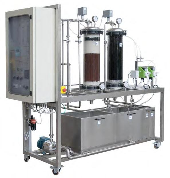
Process Control Training Plant Model PCT 023

The Level Process Module is designed to aid students in conducting level calibration work. The module uses laboratory demonstration system as basis for the performance of liquid level. The unit includes a pump that pumps water into a transparent container, whereby the content and measurement reading of this transparent liquid -level tank can be clearly observed. The switch box contains an industrial controller, a chart recorder and all required electrical measuring equipment. The level of the water in the tank is determined using an electronic pressure sensor. Excess water returns to the tank via an overflow.

Item Description

Sci-tech Process Control Training Plant Model PCT 023 offers comprehensive actual plant type training and consists of:
– Level
– Pressure
– Flow
– Temperature

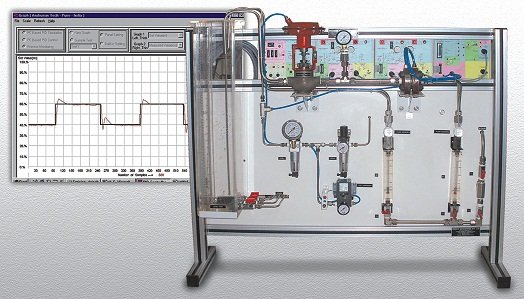
Technical Specifications

* Computer Interface panel (CIP/PCT1)
• Connects to PC (P4/XP) parallel port through 25 pin M to F cable / 1.5mtr.
• 4 ADC channels I/P: 0 to 2.5V FS with 1no input simulation pot. 1 DAC channel O/P 2.5V FS.
• V to I function block: I/P 0 to 2.5V & O/P 0-20 or 4-20mA (100W load) switch settable.
• I to V function block : I/P 4 to 20mA & O/P 0 – 2.5V
• USB converter to interface 25 pin D connector on CIP panel to USB using PIC18F microcontroller 28 Pin SOIC enclosed in 25 Pin D shell using Type A to mini B cable.
• Optionally hardware module of square root extractor is provided so that PLC/Panel mount PID may be interfaced.
* Instrumentation Power supply cum Multichannel DPM panel (EMT 8)
• ±12V/500 mA, +5V/300mA, Unregulated 17V dc/750 mA, line synchronizing signal, 13V / 3 Amp.
• Multi channel DPM for digital display of process parameters.
• 20 pin FRC power bus to supply power to neighbouring panels.
* Thyristor Actuator cum signal conditioning panel (TAP) / CE2 x 2Nos.
• Optionals:Thyristor bridge based 0-200V/3A using cosine firing circuit, I/P 0 to 2.5Vdc.
• Supports signal conditioning for RTD, Pressure sensor with Instrumentation Amplifier & flow sensor (water / air) with F to V converter to generate 0-2.5Vdc (FS).
• Optionally facilitates closed loop control experiments based on temperature, light intensity, speed measurement using built in P/PI controller as well as external Analog / Digital PID controller.
• 2No. panels may be needed to cover signal conditioning needs of the selected process.
* PC (P4/XP/WIN7/FAT32) based digital base PID controller (PC not in scope of supply but P4/XP/WIN7 with parallel /USB port needed)
• Online monitoring / Data acquisition / PID Software on Installable (CD) works under XP, WIN7. PC with parallel port / USB needed.
• Operating modes
a) Simulator Mode: Tests data stored in files (*.txt) Draw graph for all P,PI,PD & PID modes.
b) Process Monitoring Mode : Draw graphs of analog data presented at CH 0 & CH 1 of CIP. Cursors for X & Y axis for measurement & online graphs saving for reproduction.

c) PID controller Mode
• PID controller with parameter like Integral Time Ti (0.01-64000), Sampling Time Ts(0.1-99.9), Derivative Time Td(0-99.9), Proportional Band Pb(1-999), Derivative Gain Kd(1-999), Set Value Rn(0-99.9), PID output Upper Limit Uh(0-99.9), PID output Lower Limit Ul (0-99.9).
• Facility to set units for output viz. (%) oC , RPM, V, mm, LPH, kg/cm², msi/cm, Degree. Optionally experiments with advance process control scheme viz; Ratio, Cascade, feedforward with Aux PID, Ratio station & FF transfer function calculator, Alarm setting, ON/OFF control, square root extractor for Orifice.
• Function Generator : Sine / Triangular / Square wave generator with frequency 0.01 Hz to 1 Hz, Amplitude is 0 to 2.5 V i.e. 0 – 100%.