The wiring of electrical components for the start and operation of refrigerant compressors is a typical task in the field of refrigeration. Safety aspects also play an important role. With Sci-tech Electrical Connection of Refrigerant compressors Model RAC 083 this knowledge and these skills can be acquired. All components are operated and tested with mains voltage to provide high relevance for practice.
Features
* Correct electrical connection of a refrigerant compressor
* Use of a real refrigerant compressor
* Design and investigation of a safety chain
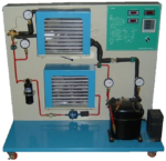
The electrical components for the start and operation of the refrigerant compressor are arranged clearly visible. The electrical connection of the individual components is made with cables via the lab jacks. The components are e.g. the capacitor and start-up relay necessary to start the motor. The circuit diagram on the front panel enables the easy allocation of the individual components. The refrigeration circuit with compressor and receiver enables the checking of the pressure switches on the intake and delivery side of the compressor. The pressure is set via valves and the pressure switch tripped. Two manometers enable the monitoring of the pressure curve. If one of the pressure switches trips, the current supply to the compressor is interrupted. The wiring and checking of other typical components of the safety chain, e.g. circuit breaker and automatic fuse, is also carried out. The well-structured instructional material sets out the fundamentals and provides a step-by-step guide through the experiments.
Empowering Education Through Innovation