Computer Interfaced Electronic Trainer Model ETR 011

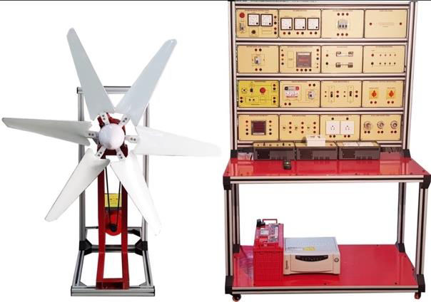
Aesthetically designed injection moulded electronic desk (Master unit) with common experiment resources like Power supplies, Function Generator, switches, indicators, DPM etc. while the slot will carry replaceable expt. Panels 4 mm sockets in a arranged on a grid of 19 x19mm to receive plug in components.

Item Description

– Optionally computer assisted Training through use of Lab view® based executables supported by variety of virtual instrumentation like toggle switches, leds etc.
– Emphasis on troubleshooting skills through fault switches.
– Replaceable panel connects to computer I/F on master unit through 64 pin (Euro connector)
– Set of Users Guide provided with each Unit

Technical Specifications

Power Supply:

DC Supply – +5V / 1A. & ±12V, 500mA
3 to 18V DC (Variable)/ 1A (Isolated) -2 nos. With short ckt & overload protection.
Both kept isolated to facilitate either 3 to 36V or +18Vpower supplies etc.

AC Supply – 12-0-12V AC, 150mA. Short circuit protected

Function Generator
Waveform Sine- Triangle & TTL /O/Ps

Frequency – 1 Hz to 1MHz in 6 ranges, with amplitude & frequency control pots.

Voltage & current – 15V p-p max. (Sin / TRG) open ckt. (7.5Vpp into 50 ohm termination)

Optional I/ps (on Hind Plate):

AM -I/P voltage + 5V (100%
modulation)O/P – For 0V
(min), + 5V (max.), – 5V
(Phase reversal of O/P)

FM- I/P voltage ± 400
mV ( + 50%
modulation)

FSK – I/P upto 500Hz,
+ 4.5 square wave

3-Phase voltage Generator – 6Vrms/50Hz,/120 degree phase shifted 3 O/ps, max 10mA loading

Frequency Counter (Optional) – 4 digit frequency display, Max I/p -10Vpp, 300mV sensitivity, Range: 2MHz. Max.

Logic input switches & status Indicators – Bi-Colour buffered LED status indicators 8X2 nos for High/Low indication. Input Data Switches (Slide switches x 8nos.)

Computer Interface:

Digital I/O – Using parallel port or optional USB port (through converter supplied)8 I/p, 8 O/P, 8 Bidirectional I/O Lines (TTL), opto isolated Adaptor to prevent damage to pc

Analog I/P – 2nos. of +9V ADC channels, 2nos. of 0-2.5V ADC channels, Max BW- 1KHz

Analog O/P – O/p 0-10V max (optionally 0-2.5V), max. load 10 mA

Pulsar switches (2no.) – with four debounced outputs (TTL), A, A, B, B

Logic probe – to detect High/Low, level TTL pulses upto 1MHz, with bi-colour LEDs to indicate status.

7 segment display – 2-digit red led 7 segment with built in BCD to 7 segment decoder(TTL)

Onboard DPM (1no.) – provided with mode/range selection, DC volt – 2V/20V & DC current – 2mA/200mA