Salient Features
- Each of following independent modules of Sci-tech Applied Power Electronic Trainer Model ETR 006 may need a few set of associated panels (4 nos. typically) which are mounted in a light weight sturdy aluminum flat demo panel system.
- Facilitates easy and safe wiring by students due to 4mm sturdy shrouded banana patch cords and shrouded socket arrangement for high voltage circuits.
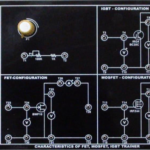
- Each panel has ABS molded plastic sturdy enclosure, and colorful screw-less overlays showing circuit diagram & its connection tag numbers for easy understanding and connections.
- Computer interface panel & ‘SciCal – Labview’ software optionally provided to suit
Specific requirements of the set up.
- Set of Instructor Guide & Student Workbook.
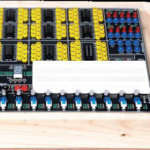
- Aluminum rack: of 1 X 4 matrix used as flat panel demo panel system to house 4 panels needed for the trainer ordered.
- Dimensions : 500(H)X910(L)X300(D)mm
- Power Analyzer, Panel : The micro-processor-based instrument Displays, Stores, and Communicates up to 63 major electrical parameters including true RMS Voltage, Current, PF, Frequency, Active Power, Reactive Power, Apparent Power, Active Energy, Reactive Energy, Apparent Energy, Total Harmonic Distortion (THD), Maximum Demand. The instrument offers simple user-friendly programming of Voltage, Current and Power measurement parameters using a menu driven interface. Status of all parameters can be viewed on LED Displays. The instrument offers the option of digital RS485 communication.