Empowering Education Through Innovation
Empowering Education Through Innovation
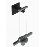
Sci-tech Slotted Link Mechanism Model MT 137 is an example of a quick-return mechanism, capable of transforming circular motion into reciprocating motion. It is made of aluminum and consists of a rotary element (graduated disk), called crank, connected to a rigid bar, called connecting rod. When rotating the crank, the connecting rod moves back and forward. The rotation motion of a crank or crankshaft causes a rectilinear reciprocating motion of a piston or plunger. It is a reversible system through which the connecting rod can be displaced by turning the crank and the other way round. If the connecting rod generates the input motion (as a piston in a car engine does), the crank is forced to rotate.
Features
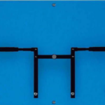
Sci-tech Slotted Link Mechanism Model MT 137 is a quick-return mechanism. It is used in some modelling machines in which the cutting tool is slow in one way and fast in the return. This mechanism is a combination of an inversion of the slider-crank mechanism and a slider block. It is a mechanism capable of transforming circular motion into reciprocating motion.
Sci-tech Slotted Link Mechanism Model MT 137 is an example of a quick-return mechanism, capable of transforming circular motion into reciprocating motion. It is made of aluminum and consists of a rotary element (graduated disk), called crank, connected to a rigid bar, called connecting rod. When rotating the crank, the connecting rod moves back and forward. The rotation motion of a crank or crankshaft causes a rectilinear reciprocating motion of a piston or plunger. It is a reversible system through which the connecting rod can be displaced by turning the crank and the other way round. If the connecting rod generates the input motion (as a piston in a car engine does), the crank is forced to rotate.