Pelton Turbine Demonstration MODEL FM 16

Sci-tech Pelton Wheel Turbine Demonstrator Model FM 16 is an impulse transferred by the impact of water jet on the runner fitted with buckets. The change in the momentum of water jet results in the force on the buckets which turns the runner. The torque developed is converted into useful work. Pelton turbines are used in hydro-electric power plants operating with water source available at high heads and low volume flow rates. It is essential for students to understand the characteristics of Pelton turbines. The Sci-tech Demonstration Unit is necessary equipment machinery for fluid mechanics educational institutions. Pelton turbine turbine and energy and it’s operations and performance Pelton Turbine for hydraulics laboratory is very important part of syllabus of fluid mechanics in educational institutions.

Item Description

Sci-tech Pelton Wheel Turbine Demonstrator Model FM 16 is an impulse transferred by the impact of water jet on the runner fitted with buckets. The change in the momentum of water jet results in the force on the buckets which turns the runner. The torque developed is converted into useful work. Pelton turbines are used in hydro-electric power plants operating with water source available at high heads and low volume flow rates. It is essential for students to understand the characteristics of Pelton turbines. The Sci-tech Demonstration Unit is necessary equipment machinery for fluid mechanics educational institutions. Pelton turbine turbine and energy and it’s operations and performance Pelton Turbine for hydraulics laboratory is very important part of syllabus of fluid mechanics in educational institutions.

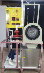
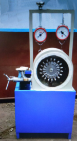
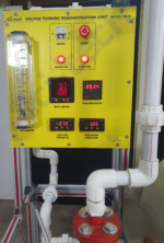
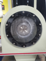
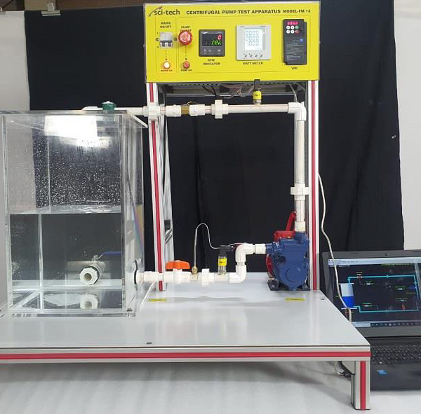
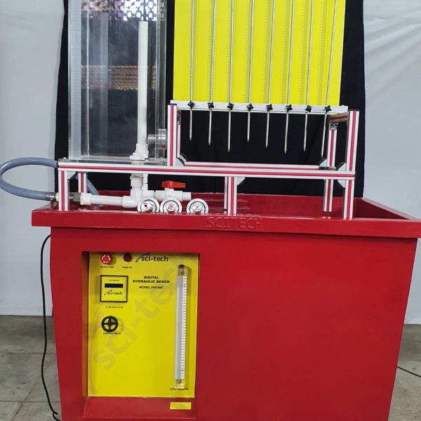
The Sci-tech Pelton Wheel Turbine Demonstrator Model FM 16 has been designed to enable students to study the operation and characteristics of a typical Pelton turbine. The unit has to be connected to the Sci-tech Hydraulic Bench FM 100. The runner is mounted on a horizontal shaft and is fitted with buckets. A horizontal jet of water issuing from the nozzle produces a force on the bucket. The flow rate through the nozzle can be adjusted by varying the position of the needle valve inside the nozzle. The output of the turbine is measured using a brake band friction dynamometer. Digital RPM indicator with proximity sensor is provided to measure shaft speed. The runner and nozzle assembly is enclosed in a casing. The bottom of the casing is open and allows water leaving the buckets to drain. The front face of the casing is made transparent using Perspex to allow observation of turbine during operation. The unit is a compact and designed for quick and easy setting up of experiments. All components and instrumentation are placed in robust and mobile frame.

Technical Specifications

Important Features and Specifications
PELTON WHEEL TURBINE TEST RIG (1KW TYPICAL) (CC type)
a)
 Number of blades: 16
 Wheel diameter: 120mm
 Bucket depth: 14mm
 Jet diameter: 10mm
 Shaft diameter: 10mm
 Rated speed: @ 2000 rpm
b) Pelton Turbine designed for laboratory experimental purpose & to conduct test under constant
head of the following specs. Net Head: 25 M,
Discharge :500 LPM, Normal Speed : 1000 RPM, Power:1 KW
The unit consists of the following:
Casing: Of close grained cast iron with large circular observation window.
Runner: Of gun metal fitted with ground & accurately finished buckets.
Shaft: Of steel ground to close tolerance.
Spear Road: Of gun metal fitted with a brass opening & iron wheel for adjustment.
Inlet Pipe: Of close grained C.I. arranged so that the inlet can be either vertical or horizontal.
Brake Arrangement: Consists of a cast iron brake drum machined & polished, cooling water supply
pipe from the turbine inlet, internal scoop, discharge pipe, spring balance rope brake & loading dead
weights.
c) Centrifugal pump set suitable for the supply of water for the size of 2“ (50mm) to discharge 500 LPM at a total head of 25 m. coupled to 2 HP, 1440/2880 RPM induction motor 3 Ø, 440 V AC. supply
d) Flow measuring Unit: A 50 mm (2“) Venturi meter/Orificemeter with double column differential
manometer (Without Mercury) on a panel board to measure the difference of pressure.
e) Reservoir of size 0.5 m length x 0.5 m width x 0.5 m. height with drain valve of ½ ” size & a bend.
f) Starter, Switch, Digital speed indicator, Pipe line with gate valve & foot valve etc.
g) Strong iron stand to support the unit.

TECHNICAL DETAILS
The analogue output data is digitised and transferred to a computer using the standard USB (Universal Serial Bus). This allows any standard modern Windows computer to be used, including notebooks, and does not require any internal access to the computer.
The equipment is supplied complete with a USB lead for connection to the computer. The FM 16 Turbine Demonstration Unit interfaces to the computer via the provided devices and the USB port of the computer. Also available is a software driver that allows the outputs to be read in other software programs, such as Labview.
1. 3- ph. electrical supply, 440 V, 50 Hz.
2. Water supply and drainage.

Experiments

  • Study of construction of Pelton turbine
  • Determination constant head characteristics curve
  • Determination of constant speed characteristics curves.
  • Determination of constant efficiency curves.
  • Iso-performance curves

The manual describing the theoretical and practical aspects of the apparatus, operation and
maintenance, analysis of results and sample of results will be supplied with the equipment.


Model Number

FM 16