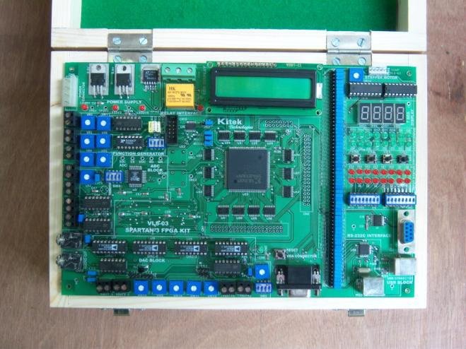
SPARTAN-3 FPGA TRAINER KIT Model VLS-03
CPU: SPARTAN -3 FPGA , 400 k logic cell SPARTAN -3 FPGA in PQ208 Package
SKU:
ad7cd261985c
Categories: Microprocessor Trainers, Trainers, VLSI TRAINERS
Analog Input Interface
– Four channel Analog Inputs using 12 bit AD7891 ADC
– 500Khz Sampling rate
– Thermister interface through channel-5 of AD7891.
– Additional Stereo Jacks are provided for Audio Input
* Analog Output Interface
- Four channel Analog Outputs using four 12 bit AD7541 DAC
- 100 ns conversion time
- Additional Stereo Jacks are provided for Audio Output.
* Function Generator (using IC 8038).
- Provides Sine, Square and Triangular waveforms outputs.
- Frequency variable from 60-200 KHz.
- One Anti-aliasing filter at the input of Analog to Digital converter.
- One Reconstruction filter at the output of Digital to Analog converter.
* Display
- Four digit seven-segment LED display.
- 16x2 Alphanumeric LCD Display
* On board Interfaces
- 16 Way Input DIP switches.
- 4 push button switches
- PS/2 Keyboard Interface
- 12 bit, 512 colors, VGA display interface port.
- RS-232C Serial interface using MAX3223 brought out on a 9-Pin D- Type connector.
- USB Interface using USB Controller FT245BM
- Stepper Motor interface using 12VDC, Steps/Rev-200 motor with step angle of 1.8º
- Single Pole Double Throw SPDT Relay.
* LED Indicators ( 38 onboard LEDS)
- 16 output LED’s (OL 0 – OL 15).
- 16 input LED’s (IL 0 – IL 15).
- One Done LED
- Three Power ON LED’s (LED 5V, LED 3V3, LED 2V5).
- Two Relay LED’s (RNO, RNC).
* User selectable configuration modes.
* Free IO lines: 11.
* Clock Oscillator:
- 4 MHz crystal clock oscillator.
- Socket Provision for an auxiliary crystal oscillator clock source.
* JTAG port
- JTAG download cable (parallel III) interface.
* Power Supplies
- 5 volts regulated power supply provided along with the board.
- On board 3.3V, 2.5V, 1.2V regulators.
- FPGA supplies viz. Vccint & Vcco are generated on board. In-Built Power Supply of
+5V/1.5A, ±12V/250mA
* User’s Manual with 25 sample experimental programs


