Process Pilot Plant for Level Control Trainer Model PCT 104

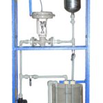
Sci-tech Process Pilot Plant for Level Control System Trainer Model PCT 104 is designed to demonstrate various aspects of control engineering using a level system to control the flow of water delivered by a pump to the level tank. The system incorporates the standard industrial components.

SKU: 179f0ee261c3 Categories: ,

Features
– Compact and sturdy construction
– Easy and versatile operation
– Self contained system
– Incorporates standard industrial components
– Comprehensive instrumentation

The plant consists of following components, 1) Sump Tank: 20 lit capacity, transparent, acrylic 2) Level Tank: 15 lit capacity, Transparent, acrylic 3) Piping material: corrosion resistant Fusion PPR piping 4) Pump: Centrifugal pump capable of delivering 1000 LPH flow at 3 bar pressure, make Kirloskar, Q-Tech, Tullu or equivalent, 230 V AC operated 5) Pneumatic Control Valve: ½”, equal percentage characteristic. Input 3 to 15 psi. Flanged connection. Air to open type, Body material cast iron or better, Mounting: flange type, Actuator type: diaphragm, (Note: actuator and body assembly should detachable type not a single mould or miniature), Seating: double seated with upper and bottom bonnets, Make Samson Controls, Dembla or equivalent 6) Head type level sensor transmitter with HART protocol. Range: 40 cms of WC, Supply 24 V dc. Output: 4- 20 mA 7) I/P Converter: Input 4-20 mA, Output: 3-15 psi 8) Airs filter Regulator: ¼” connection size, transparent bulbs, with pressure gauge. Input: 0-10 kg/cm2, regulated supply: 0-2 kg/cm2. Filter: 25 micron. 9) Colored Mimic depicting the process, size: 1000 mm x 700 mm (minimum) 10) HART Indicator: With LCD indicator. 15 units having HART protocol can be connected to this one unit. 11) PID Controller - With HART protocol enabled - LED/LCD display, display color green/black, for PV in operation mode, Set contents in setting mode - LED display, display color red, for SV, OUT, PID, AL1, AL2 in operation mode - Full Multi-range input (Thremocouple, RTD, DC Volts and current defined by input selector switch) - Control output multi-function (On-Off pulse, SSR drive, current, current defined by input selector switch) - Auto tuning and Fuzzy functions - Sampling cycle: Approx. 0.2 sec - Facility to bypass PID mode (Also known as Auto/Manual Mode) - LED for Alarm display - Hard changeover for switchover from manual to auto mode. - 230 V AC operated 12) Interface Unit: 8 channel analog input, 4-20 mA/0- 20 mA 1 channel analog output, 4 –20 mA Interface with PC through USB port 13) Control Panel Box: To house electrical as well as instrumentation. MOC: MS 14) PC: Latest specifications with pre-loaded Windows and control software 15) Software: Lab view Based SCADA Software for controlling the parameter. Software should be capable of Feedback, Feed forward, Cascade, Ratio and On- off control schemes. The software should have following facilities, - Real time measured parameter versus time graph - Display of measured parameter, output and set-point in bar graph format - Liner scale for setting set point of PID