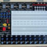
DIGITAL/ANALOG TRAINER KIT MODEL DTK-01E

  • Bread Board Area
    – It consists of Four Distribution Strip of 100 tie points and Two Terminal Strip of 640 tie points
    totaling 1680 tie points.
    – Located at the center of the PCB, with provision to remove it.
    – Can be replaced with the Experimental Boards mentioned below.
SKU: b07d80eb3f1a Categories: , ,
  • Indicators
    – 16 TTL/CMOS Logic Level Inputs with Dual Color LED indication for logic low and logic high
    – 16 LED for output indication.
    – 2 Digit 7 Segment Displays with BCD to Seven segment Decoder
    – LED BAR Graph with 10 LED Indicators to display 0-5V input
  • Onboard Interfaces - DPM provided with mode selection: DC volt/current 200mA/200V - 8 ohms, 0.5 Watt Speaker - Variable potentiometers of 1K, 10K 100K provided on board - Computer Interface adapter (25 Pin D-Type connector) outputs of which are brought out on 25 Nos. of Banana Sockets facilitates in connecting with IEEE 488 or RS-232 Serial Port of PC - LED BAR Graph with 10 LED Indicators to display 0-5V input
  •  Fixed Clock Generator - 1Hz, 5Hz, 100Hz, 1KHz, 10KHz, 100KHz, 1MHz & 10 MHz.
  • Pulse Generator - Two No. of SPDT Pulser Switches provided. - It provides bounce less pulses of Low to High and High to Low transitions.
  • Logic Probe - Logic Probe to indicate Low/High Pulses up to 1 MHz - LED indicators to indicate Logic High, Low
  • Function Generator (using IC 8038). - Provides Sine, Square/TTL and Triangular output waveforms. - Frequency variable from 1Hz.-200 KHz in SIX steps. - Amplitude and Frequency can be varied - Output Voltage 20V p-p max.