DC Position Servo System Demonstrator Model PCT 014

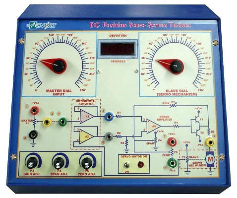
Sci-tech DC position Servo System Demonstrator Model PCT 014 is a versatile self – contained stand – alone demonstrator, useful in the study and demonstration of the principle and working of a DC position Servo System. It consists of a common potentiometer with calibrated dial as master or input transducer and a rebalance potentiometer to convert output position into a voltage signal along with specially designed DC motor with suitable coupling, Amplifiers Pre – amplifier (Differential Amplifier), Summing amplifier of adjustable Gain & Span (Error Amplifier) and Power amplifier for driving DC motor on basis of error signal.

SKU: 15296adfcb24 Categories: ,

Various controls for different parameters are provided. It is a highly accurate, highly sensitive demonstrator with good repeatability, linearity and fast response. The unit is housed in an elegant cabinet with a well spread intelligently designed multicoloured layout on the front panel. Multi – coloured test points are provided at various stages to observe waveforms and voltages. It is strongly supported by a comprehensive instruction manual complete with theory & operating details.

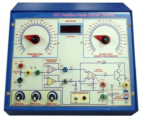
Principle : DC Position Servo System Displacement : Angular (00 to 2700) Input Transducer : Command or master potentiometer with calibrated dial (00 to 2700) Motor : Specially designed bi - directional, geared, permanent magnet armature controlled DC motor Coupling : Suitable coupling of motor to output re - balance potentiometer Instrumentation : Amplifiers Pre – amplifier (Differential Amplifier), Summing amplifier of adjustable Gain & Span (Error Amplifier) and Power amplifier for driving DC motor on basis of error signal Amplifier Gain : Controlled by the Voltage signal derived by the conversion of the output position of rebalance potentiometer into voltage signal Output : Slave dial coupled to the servo mechanism and mounted with calibrated dial (00 to 2700). Controls : 1. Master or command Control (Input potentiometer) 2. Zero adjust Control for minimum (lower limit) of angular displacement 3. Span adjust Control for maximum (upper limit) of angular displacement 4. Gain adjust Control 5. DC Servo Motor ON / OFF Control 6. Mains ON / OFF Indicators : 1. Digital Deviation (Error) Meter in Degrees 2. DC Servo Motor ON / OFF 3. Mains ON / OFF Front Facia : A well spread intelligently designed multi-coloured layout on the front panel housed in an elegant ergonomically designed cabinet Test Points : Multi-coloured Test points provided at various stages to observe waveforms and voltages Power Requirements: 230V,  10% AC, 50Hz, 1 phase Standard Accessories: A Detailed & comprehensive instruction manual complete with theory & operating details