In AC servomechanisms of the last years, the vectorial F.O.C. field- oriented control technology is dominating. Used with three-phase asynchronous motors, they allow to reach torque and speed performances, superior to those obtained with traditional scalar technology.
Sci-tech Vectorial field-oriented control servomechanism for asynchronous three-phase motor Model PCT 111 enables the student to learn, demonstrate and experiment the main concepts of field oriented control, enriching the personal theoretical background with the practical aspects of industrial design and maintenance. The power of the servomechanism, the circuit solutions, the used components, make the training program to be developed on a totally industrial product and not on a simulator.
VECTORIAL FIELD-ORIENTED CONTROL SERVOMECHANISM FOR ASYNCHRONOUS THREEPHASE
MOTOR Model PCT 111 Mainly consists of:
* An industrial vectorial inverter for asynchronous three- phase bidirectional motor;
* An external unit consisting of a three-phase asynchronous motor.
The available control modes are:
• Field orientation with speed sensor;
• Field orientation without speed sensor (Sensorless);
• V/Hz control.
The servomechanism is mounted on the aluminum structure, an innovative system for teaching presentation combining the demonstration effect with the operative functionality.
The compact unit includes:
* An electronic circuit of the equipment;
* A silk-screen printed diagram with detailed block diagram;
* A panel with controls, signaling, test points;
* A non-destructive fault simulator.
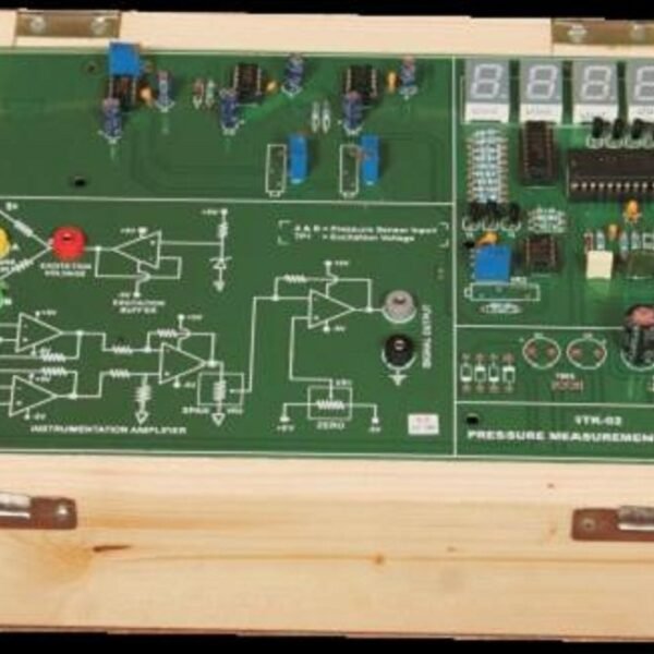
The servomechanism is connected to the external motor via an 8-pole cable. A dedicated electronic board, provided with the equipment Model PCT 111, enables the PC interfacing for data acquisition and process supervision experiences. The parametrization of the servomechanism is made with a keyboard with LCD display or via PC with dedicated software supplied with the system.
A faults’ simulation system enables the insertion of 8 different non-destructive faults through switches; the faults simulated are typical cases verified in the industrial use of the system
Empowering Education Through Innovation