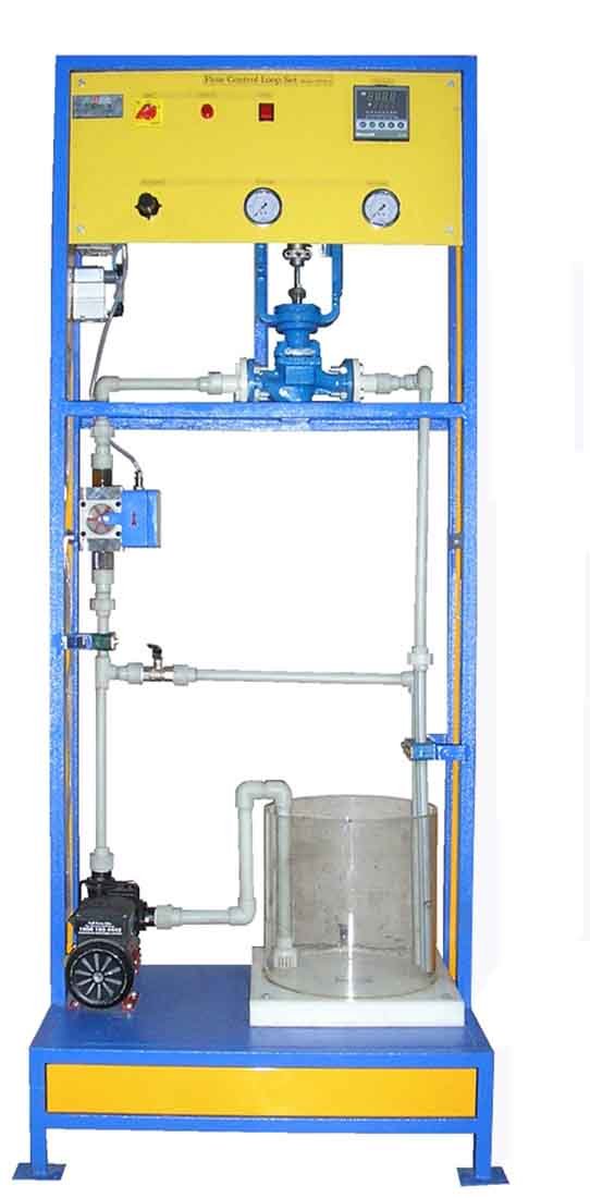
Process Pilot Plant for Flow Control Trainer Model PCT 103
Sci-tech Process Pilot Plant for Flow Control System Trainer Model PCT 103 is designed to demonstrate various aspects of control engineering using a flow control system to control the flow of water delivered by a pump. The system incorporates the standard industrial components.
SKU:
efd439a5dac5
Categories: Process Control Engineering, Trainers
Features
– Compact and sturdy construction
– Computerised analysis (Optional)
– Incorporates standard industrial components
– Comprehensive instrumentation
1) Sump Tank: 20 lit capacity, Transparent, MOC: acrylic
2) Piping material: corrosion resistant Fusion PPR piping
3) Pump: Centrifugal pump capable of delivering 1000 lph flow at 3 bar pressure, make Kirloskar,
Q-Tech, Tullu or equivalent, 230 V AC operated
4) Pneumatic Control Valve: ½”, equal percentage characteristic. Input 3 to 15 psi. Flanged
connection. Air to open type, Body material cast iron or better, Mounting: flange type, Actuator
type: diaphragm, (Note: actuator and body assembly should detachable type not a single
mould or miniature), Seating: double seated with upper and bottom bonnets, Make Samson
Controls, Dembla or equivalent
5) Flow sensor suitable to sense clean water flow rate of upto 1000 LPH. Turbine type. Supply
10) PID Controller
- With HART protocol enabled
- LED/LCD display, display color green/black, for PV in operation mode, Set contents in setting mode
- LED display, display color red, for SV, OUT, PID, AL1, AL2 in operation mode
- Full Multi-range input (Thremocouple, RTD, DC Volts and current defined by input selector switch)
- Control output multi-function (On-Off pulse, SSR drive, current, current defined by input selector switch)
- Auto tuning and Fuzzy functions
- Sampling cycle: Approx. 0.2 sec
- Facility to bypass PID mode (Also known as Auto/Manual Mode)
- LED for Alarm display
- Hard changeover for switchover from manual to auto mode.
- 230 V AC operated
11) Interface Unit:
8 channel analog input, 4-20 mA/0- 20 mA
1 channel analog output, 4 –20 mA
Interface with PC through USB port
12) Control Panel Box: To house electrical as well as instrumentation. MOC: MS
13) PC: Latest specifications with pre-loaded Windows and control software
14) Software: Lab view Based SCADA Software for controlling the parameter. Software should be capable of Feedback, Feed forward, Cascade, Ratio and On- off control schemes. The software should have following facilities,
Real time measured parameter versus time graph
Display of measured parameter, output and set-point in bar graph format
Liner scale for setting set point of PID
Circular knobs for setting values of P, I and D parameters
Facility to start/stop data logging and storing/retrieval of logged data
Facility to view logged data in graphical format
24 V dc. Output: 4- 20 mA. SS Blades, SS body, threaded connection, 2 wire type.
6) I/P Converter: Input 4-20 mA, Output: 3-15 psi
7) Air filter Regulator: ¼” connection size, transparent bulbs, with pressure gauge. Input: 0-10
kg/cm2, regulated supply: 0-2 kg/cm2. Filter: 25 micron.
8) Colored Mimic depicting the process, size: 1000 mm x 700 mm (minimum)
9) HART Indicator: With LCD indicator. 15 units having HART protocol can be connected to this
one unit.
RELATED PRODUCTS
Cyclonic Seperation Trainer ENV 001
Rated 0 out of 5
Deep Filter Bed Column ENV 002
Rated 0 out of 5
Filterability Index Unit ENV 005
Rated 0 out of 5


