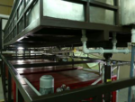
Sci-tech Rainfall Run off Simulator Model FM 73 demonstrates some of the major physical processes found in hydrology and fluvial geomorphology, including: rainfall hydrographs for catchment areas of varying permeability; the abstraction of ground water by wells, both with and without surface recharge from rainfall; the formation of river features and effects of sediment transport. Realistic results can be obtained from this small scale, floor standing apparatus, which can be conveniently located and requires no special services. The unit comprises a sand tank, made of stainless steel, measuring 6 meters by 2 meter. Water will be input to the sand tank or from two drains buried in the sand at either end of the tank. The water is output either from an outlet tank and flow measurement system located at the end of the main sand tank, from one or both of the two wells located in the tank, or one or both of the French drains. A large plastic sump tank is located under the sand tank. Ground water table levels (phreatic surface) are measured using twenty tapping points in the sand tank, configured in a cruciform pattern, and displayed on a manometer bank. The river inlet tank is use to still the flow, and a shaped channel section to provide formed flow conditions into the sand tank.
Sci-tech Rainfall Run off Simulator Model FM 73 demonstrates some of the major physical processes found in hydrology and fluvial geomorphology, including: rainfall hydrographs for catchment areas of varying permeability; the abstraction of ground water by wells, both with and without surface recharge from rainfall; the formation of river features and effects of sediment transport.
Realistic results can be obtained from this small scale, floor standing apparatus, which can be conveniently located and requires no special services.
The unit comprises a sand tank, made of stainless steel, measuring 6 meters by 2 meter. Water will be input to the sand tank or from two drains buried in the sand at either end of the tank. The water is output either from an outlet tank and flow measurement system located at the end of the main sand tank, from one or both of the two wells located in the tank, or one or both of the French drains. A large plastic sump tank is located under the sand tank.
Ground water table levels (phreatic surface) are measured using twenty tapping points in the sand tank, configured in a cruciform pattern, and displayed on a manometer bank. The river inlet tank is use to still the flow, and a shaped channel section to provide formed flow conditions into the sand tank.
The subsurface flow inputs are via two drains, buried in the sand at either end of the tank. These French drains extend the full width of the tank. Each drain can be configured as an inlet or an outlet to permit a wide variety of hydrological demonstrations. Two variable area flow meters with integral adjusting valves are used to control and measure the various flows into the tank.
The use of self-sealing quick release fittings allows the system to be configured in a variety of different ways, enabling a wide range of demonstrations.
The two flowmeter have different ranges, further enhancing the flexibility of the overall system. Pressure regulators and filters are incorporated in the water supply lines, minimizing system disturbances. The outlet tank is located at the end of the sand tank, and is used for hydrographs, run-off and river formation demonstrations. A different height plate is used to adjust the outlet conditions.
The outlet tank comprises a sand trap, water stilling system and a flow measurement device. The flow measurement is performed by measuring the height of the water in the measuring tank, using the time required to fill the water. The sand trap is configured to allow the sediment to be collected in a sieve. In this way the amount of sediment collected over a period of time can be measured.
Optionally ‘Sci-Cal’ DAQ interfacing, data acquisition makes it possible to record measured values during experiments to process and store data on PC.
Specifications
Base Stand: This is made up of M.S. Square pipes &Aluminum bonded sheets.
S.S.Tank for Experiments:
S.S. Experimental Tank ( considered here is 6meters long x 2 meters wide), acting as a catchment area for rainfall hydrographs and wide range of experiments. It consists of a 20 numbers of tapings at the centre of the bottom, as pressure points, for connection of the PU tubes proceeding towards the manometer. These connections to the manometer give the hydrographs for wide range of experiments
Flow meter: 3 Flow rate of water through Tank are measured using Flow meters, paddle wheel type; capacity is 4000 LPH & 2 flow rate meters of capacity 2000 LPH.
Level Sensors: Level sensors are used to measure the level of the water in the experimental tank at the different points. Range: 0-500 mm; Output: 4-20 mA; Working principle: Change in Capacitance
Monobloc Pump: Monobloc pump is used for circulating the water for wide range of experiments from experimental tank. Capacity: 4000 lph@ 6m of head; Motor Capacity: 1 hp or 0.75 KW; Pipe Size: Suction and delivery 25 mm X 25 mm
Measuring Tank: Measuring tank is used to measure the flow rate of water through the experimental tank. This tank can also use to plot the rainfall hydrographs through the flow rate measurement Vs Time from the measuring tank. Capacity: 75 liters; Material: Acrylic
Load cell Unit: Load Cell Arrangement is affixed below the measuring tank with the stand mounted on load cell which is compression type load cell used for measuring the amount of sediments carried from runoff and collected in the measuring tank. By taking the difference of the weights measured we can calculate the amount of sediments carried through the erosion and run off.
Capacity: 150 Kg; Accuracy: 0.01 kg; Button: Set Zero and Span with converter; Type: Compression and Tension (S type)
Hydraulic Lifting Cylinder for Tilting Arrangement: Hydraulic Jack Tilting Arrangement is done in the trainer for lifting the Experimental tank in upward and downward direction for adjusting the slope of catchment area as per user’s requirement.
Multi tube Manometer: precision and highly accurate ‘Multi-tube Manometer’ on the front side that is exactly in level of the experimental tank. It consists of the 20 tubes to measure the water level in the tank. The pressure at the groundwater level in the sand tank, which is kept in the steel experimental tank can be measured through the manometer scale. Range: 0-500 mm; No. of Tubes: 20 tubes; Material: Acrylic
Control Panel consists of:
- Mains ON/OFF; -Mains Indicator; - Water Pump ON/OFF; - Hydraulic Motor ON/OFF and UP & Down press button for tilting arrangement; - Solenoid Valves ON/OFF Switches.
Experiment Possibilities
Services required
Empowering Education Through Innovation