Induced Draft Cooling Tower Model Model THC 005

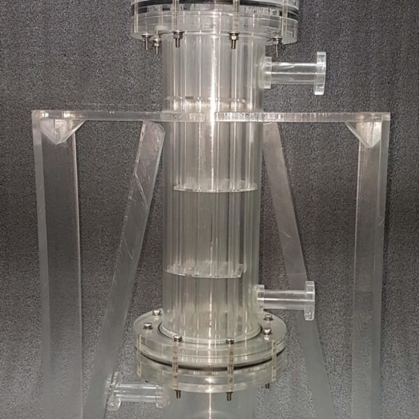
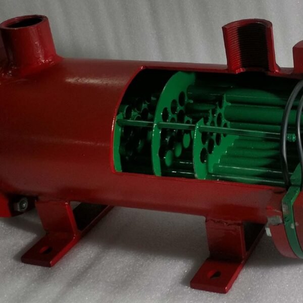
– Made in actual materials allowing study of internal/external construction
– Working model in operational dimensions
– Uses real-time pump for water-pumping
– Durable and easily cleanable model

Item Description

Induced draft cooling towers, are constructed such that the incoming circulating water is dispersed throughout the cooling tower via a spray header. The spray is directed down over baffles that are designed to maximize the contact between water and air. The air is drawn through the baffled area by large circulating fans and causes the evaporation and the cooling of the water.
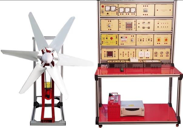
Technical Specifications

– Fills
Honey combed PVC fills are high performance heavy duty, law weight and excellent resistance to corrosion.
These offer a striking balance between maximum heat transfer surface area vis-à-vis minimum restrictions to air flow.
– Fan
The Axial flow fan consists of cast Aluminum or FRP variable pitch aerofoil blades fitted on a M.S. hot dip galvanized hub with S.S. “U” bolts & nuts.
The balanced fan assembly is mounted directly on the shaft of weather proof, flanged motor. Both axial (propeller type) and centrifugal fans are used in towers. Generally, propeller fans are used in induced draft towers and both propeller and centrifugal fans are found in forced draft towers. Depending upon their size, propeller fans can either be fixed or variable pitch.
A fan having non-automatic adjustable pitch blades permits the same fan to be used over a wide range of KW with the fan adjusted to deliver the desired air flow at the lowest power consumption. Automatic variable pitch blades can vary air flow in response to changing load conditions.
– Nozzles
These provide the water sprays to wet the fill. Uniform water distribution at the top of the fill is essential to achieve proper wetting of the entire fill surface. Nozzles can either be fixed in place and have either round or square spray patterns or can be part of a rotating assembly as found in some circular cross-section towers.
– Air Inlet
This is the point of entry for the air entering a tower. The inlet may take up an entire side of a tower (cross-flow design) or be located low on the side or the bottom of the tower (counter-flow design).
– Water Distribution
These spray water to wet the fill. Uniform water distribution at the top of the fill is essential to
achieve proper wetting of the entire fill surface.
Nozzles can either be fixed and spray in a round or square patterns, or they can be part of a
rotating assembly as found in some circular cross-section towers.
– Drive Shaft
Cooling tower drive shafts used for transmit power from the motor’s output shaft into the gear reducer’s input shaft. Drive shafts must also be corrosion resistant due to the harmful environment in which they operate.
– Drift Eliminators
These capture water droplets entrapped in the air stream that otherwise would be lost to the atmosphere. Cooling tower drift eliminators and heavy duty drift eliminators are parts of a cooling tower that are designed to remove droplets of water from the air and minimize loss of process water. Drift eliminators cause the droplets and air to change direction suddenly. This process causes the water to become separated from the air and put back into the cooling tower.