Home
Products
About us
Contact us
Select category
Select category
Electrical & Electrical Machines Trainers|Trainers
Other products
Trainers
Aerodynamics
Automotive
ABS and Braking Systems Trainers
Air Conditioning Trainers
Components & Other Trainers
Cut Sections of Automobile Parts
Engine and ignition trainers
Engines & Transmission
Steering
Technology
Boilers & SteamGens
Electronics Trainer
Environmental Trainers
Fluid Mechanics
Hydraulics
Microprocessor Trainers
8051 Micro-Controller Trainer Series
8085 MICROPROCESSOR TRAINERS
8086 MICROPROCESSOR TRAINERS
LOGIC TRAINERS SERIES
Series MIC 005 SERIES
VLSI TRAINERS
Other Trainers
Process Control Engineering
Refrigeration Engineering
Strength of Material
Telecom Trainers
Advance Digital Communication Lab Model Series TCM 002
Advanced Communication Lab Series Model TCM 001 Series
ANTENNA TRAINER SERIES TCM 004 Series
BASIC COMMUNICATION LAB TCM 005 Series
FIBRE OPTICS COMMUNICATION LAB TRAINERS TCM 008 Series
Thermodynamics
Cutaway Models
Search
0
Wishlist
☏ Talk to us
Menu
Contact us
Click to enlarge
Home
Trainers
Electronics Trainer
Digital Electronics Trainer Model ETR 001
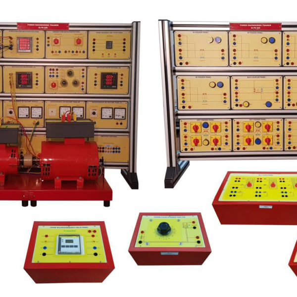
Electrical Over & Under Voltage Protection Relays Trainer Model ELTR 002
Back to products
Analogue Electronics Trainer Model ETR 002
Digital Electronics Trainer Model ETR 001
Specifications
16 TTL/CMOS Logic Level Inputs with LED indication.
16 LEDs Logic Level Indicators for outputs.
Two nos. of BCD Seven Segment Display.
Fixed Clock Generator of 1Hz, 10Hz, 100Hz, 1KHz, 10KHz, 100KHz & 1MHz.
Facility for Single Pulser Generation by a push button switch.
Logic Probe facility provided with LED indicator and one Seven Segment Display to indicate Logic High, Low and Tri-state.
On-board general purpose 5 Nos. of 16 Pin Socket & 1 No. of 20 pin Socket.
On-board 630 TIE point Bread Board. Fixed DC Power Supply: +5Vm & ±12V .
Interconnections
All interconnections are made using 2mm banana Patch cords.
All ICS are mounted on IC Sockets.
Bare board Tested Glass Epoxy SMOBC PCB is used.
High impact plastic enclosures.
Set of 2mm Patch cords for interconnections.
User’s Manual with sample experimental programs
Add to wishlist
Request for Callback
Send Enquiry
SKU:
d4458d3e97e8
Categories:
Electronics Trainer
,
Trainers
Description
Technical Specification
Specifications
16 TTL/CMOS Logic Level Inputs with LED indication.
16 LEDs Logic Level Indicators for outputs.
Two nos. of BCD Seven Segment Display.
Fixed Clock Generator of 1Hz, 10Hz, 100Hz, 1KHz, 10KHz, 100KHz & 1MHz.
Facility for Single Pulser Generation by a push button switch.
Logic Probe facility provided with LED indicator and one Seven Segment Display to indicate Logic High, Low and Tri-state.
On-board general purpose 5 Nos. of 16 Pin Socket & 1 No. of 20 pin Socket.
On-board 630 TIE point Bread Board. Fixed DC Power Supply: +5Vm & ±12V .
Interconnections
All interconnections are made using 2mm banana Patch cords.
All ICS are mounted on IC Sockets.
Bare board Tested Glass Epoxy SMOBC PCB is used.
High impact plastic enclosures.
Set of 2mm Patch cords for interconnections.
User’s Manual with sample experimental programs
Specifications
16 TTL/CMOS Logic Level Inputs with LED indication.
16 LEDs Logic Level Indicators for outputs.
Two nos. of BCD Seven Segment Display.
Fixed Clock Generator of 1Hz, 10Hz, 100Hz, 1KHz, 10KHz, 100KHz & 1MHz.
Facility for Single Pulser Generation by a push button switch.
Logic Probe facility provided with LED indicator and one Seven Segment Display to indicate Logic High, Low and Tri-state.
On-board general purpose 5 Nos. of 16 Pin Socket & 1 No. of 20 pin Socket.
On-board 630 TIE point Bread Board. Fixed DC Power Supply: +5Vm & ±12V .
Interconnections
All interconnections are made using 2mm banana Patch cords.
All ICS are mounted on IC Sockets.
Bare board Tested Glass Epoxy SMOBC PCB is used.
High impact plastic enclosures.
Set of 2mm Patch cords for interconnections.
User's Manual with sample experimental programs
RELATED PRODUCTS
Quick view
Add to wishlist
Deep Filter Bed Column ENV 002
Rated
0
out of 5
Quick view
Add to wishlist
Pumps: Piston – Electric Fuel – Mechanical Fuel AM 022 Series
Rated
0
out of 5
Quick view
Add to wishlist
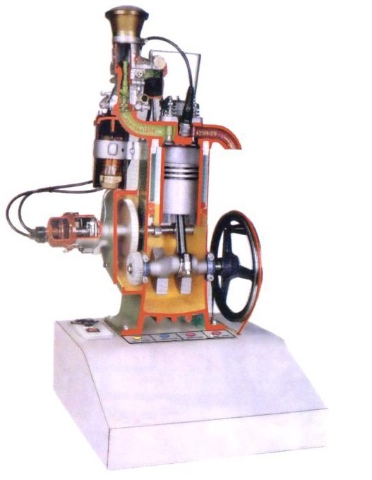
Single Cylinder Four Stroke Petrol Engine AM 047
Rated
0
out of 5
Quick view
Add to wishlist
Venturi Air Scrubber System ENV 010
Rated
0
out of 5
Quick view
Add to wishlist
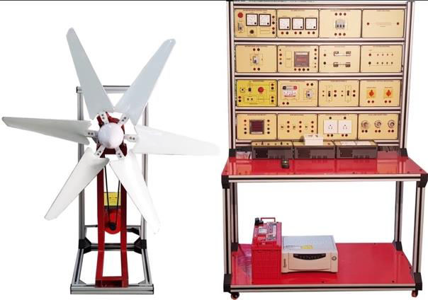
Wind Power Generation AT005
Rated
0
out of 5
Close
Search
Home
Products
About us
Contact us
Wishlist
Empowering Education Through Innovation
0
Wishlist
Send Enquiry
Request a Call Back
All Products
Request a
call back
Let's have a chat
Full Name
Phone
Email
Send
Send
Enquiry
Full Name
Phone
Product Name
Email
Send a message
Send