


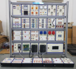


Comprehensive Power Electronic Trainer Model ETR 038
Salient Features
Ø Aesthetically designed injection molded electronic desk.
Ø Master unit carrying useful experiment resources like line Synchronized firing circuits, Power supplies, lamp load, RLC loads, Battery Charging supply etc. while the central slot will hold replaceable experiment panels.
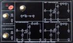
- Each multi experiment panel is secured in an ABS molded plastic sturdy enclosure and has colorful screw less overlay showing circuit & Connection through Sturdy 4mm Banana Sockets & Patch Chords.
- Set of User Guide provided with each unit.
- Built-in Measuring instrumentation.
- Modular design: Standard and small in size light weight which make the installation / uninstallation easily.
- Open Structure. The flexibility of modular form factor enables user to add addition module from different experiments provided.
- Comprehensive Learning Platform, combination of theory and practical knowledge which make student to increase the understanding of the system thoroughly.
- Comprehensive Courseware.
- Safety – built in circuit breaker to ensure total safety during hands on working.
- Reliability, Prevention on mis-operation with over current, over voltage and short circuit protection to avoid component damage and safety.
- Automatic recovery function.
- Available with or without ‘Data Acquisition Software’ interface.
SKU:
c60624163d9d
Categories: Electronics Trainer, Trainers
Ø Aesthetically designed injection molded electronic desk.
Ø Master unit carrying useful experiment resources like line Synchronized firing circuits, Power supplies, lamp load, RLC loads, Battery Charging supply etc. while the central slot will hold replaceable experiment panels.
- Each multi experiment panel is secured in an ABS molded plastic sturdy enclosure and has colorful screw less overlay showing circuit & Connection through Sturdy 4mm Banana Sockets & Patch Chords.
- Set of User Guide provided with each unit.
- Built-in Measuring instrumentation.
- Modular design: Standard and small in size light weight which make the installation / uninstallation easily.
- Open Structure. The flexibility of modular form factor enables user to add addition module from different experiments provided.
- Comprehensive Learning Platform, combination of theory and practical knowledge which make student to increase the understanding of the system thoroughly.
- Comprehensive Courseware.
- Safety – built in circuit breaker to ensure total safety during hands on working.
- Reliability, Prevention on mis-operation with over current, over voltage and short circuit protection to avoid component damage and safety.
- Automatic recovery function.
- Available with or without ‘Data Acquisition Software’ interface.
Specifications
Modular Rack Mount Design:
– Three rows of compartments designed to house training modules
– Two of these rows have full-height compartments while the other row has half-height compartments
– Each row of full-height compartments can accommodate up to three full-size EMS modules or six half-size EMS modules whereas the row of half-height compartments can accommodate up to three half-size training modules
– Separators between each bay of the workstation ensure perfect alignment of the modules
– A front-mounted release lever for each module row
– A safety locking device for each compartment
– Two safety padlocked bars on the front of the workstation prevent students from removing modules during laboratory exercises
– Holes in the rear panel of the workstation with removable cover plates for cable connection
Power Supply
Fixed single-phase and three-phase AC power, as well as fixed DC power, at the power levels required to operate the equipment used in that training program.
– Input: Line Voltage: 240/415 V
– Outputs: Fixed AC 3-Phase: 120/308 V – 5 A and Fixed DC: 120 V – 5 A
Power Thyristors
– Six (6) power thyristors (SCRs) each protected against over-currents and short-circuits
– All anodes and cathodes terminated on the faceplate by color-coded, 4 mm safety banana jacks
– Two (2) toggle switches on the faceplate which can be used to reduce the number of external connections
– Peak Inverse Voltage: 600 V or equivalent
– Maximum Current: 1 A for 240/415 V) or equivalent
– Gate Control Signals: 0-5 V pulses (TTL compatible)
IGBT Chopper/Inverter
– Seven (7) insulated-gate bipolar transistors (IGBT)
– One of the seven IGBT and a dumping resistor allows smooth dissipation of excess energy at the DC bus
– The dumping circuit to be activated through the use of a toggle switch on the front panel
– IGBTs protected against short-circuits, overvoltage, overcurrent, and overheat
– DC Bus Maximum Voltage: 840 V or equivalent
– DC Bus Maximum Current: 6 A or equivalent
– DC Bus Filtering Capacitor: 450 uF or equivalent
– DC Bus Overvoltage Protection: 880 V or equivalent
– DC Bus Circuit Breaker Protection: 6 A or equivalent
– IGBT Electronic Overcurrent Protection: 12 A
– IGBT Overheat Protection: 70-degrees Celsius (approximately)
– Dumping Circuit Voltage Threshold: 660 V or equivalent
– Dumping Circuit Resistor: 250 Ohms, 100 Watts or equivalent
– Switching Control Signals Level: 0/5 V
– Switching Control Signals Frequency Range: 0-20 kHz
– Power Requirements: 24 V, 0.16 A, 50/60 Hz
Rectifier and Filtering Capacitors
Features of this equipment include:
– One (1) Three-Phase Bridge Rectifier
– Peak Increase Voltage: 800V or equivalent
– Maximum Current: 8 A or equivalent
– Two (2) Filtering Capacitors: 165 uF - 900 VDC or equivalent
Capacitive load
– Nine (9) oil-filled capacitors arranged in three(3) identical groups for balanced or unbalanced, three-phase-delta or star (wye) loading
– Group independently varied in seven (7) steps loading
– Group connection in parallel available to create a single-phase load variable in 21 steps
– All capacitors identified by a schematic symbol, their capacitance value, as well as the current that will flow through them when connected to a nominal voltage power source and their equivalent reactance
– All capacitors within 5% tolerance of the stated capacitance value
– Nominal Voltage: 240 V – 50 Hz
– Capacitance (group): 0.66 / 1.33 / 2.65 μF at 240/415 V – 50 Hz
– Reactance (group): 1200 / 2400 / 4800 Ω at 240/415 V
Three-Phase Transformer Bank
– Three (3) power transformers
– Fifteen (15) safety banana jacks on the module front panel
– Allows connection in wye or delta configurations
– The primary and secondary windings shall be protected against over-currents and short-circuits
– Rating of each transformer: 250 VA / 1.2 A
Filtering Inductors and Capacitors
– Low Frequency Filters:
Inductance: 50 mH - 5 A - 0-2 kHz (approx)
Capacitor (Aluminum Electrolytic): 210 μF – 450 V (approx)
– High Frequency Filters:
Inductance (2): 2 mH – 2.5 A – 0-20 kHz at 220/380 V and 240/415 V (approx)
Capacitor (Metallized Polupropylene): 5 μF – 400 V (approx)
Three-Phase Filter
– Three(3) inductors, each in-line on their respective line, and a set of three(3) wye-connected capacitors
– A connection to the center point of the wye connection
– An additional capacitor (1) in series with the center point
– Inductors (3): 2 mH – 5 A – 0-2 kHz (approx)
– Metallized Polypropylene Capacitors (4): 5 μF – 400 V (approx)
Permanent Magnet DC Motor
– High-speed DC brush motor
– Equipped with a pulley half the size of the standard training system pulleys to experience power transmission with different gear ratios
– Output Power: 222 W (approx)
– Nominal Voltage: 48 V DC (approx)
– Nominal Speed: 4000 rpm (approx)
– Nominal Torque: 0.525 Nm (4.65 lbf·in) (approx)
Timing Belt
It shall consist of an industrial synchro-cog rubber timing belt.
Four-Quadrant Dynamometer/Power Supply
– Computer-based function control as well as manual function control capability using the front panel buttons
– 500 Watts or more power supply (approx)
– A variable AC and DC voltage source up to 150 Volts (approx)
– A variable current source up to 5 Amps (approx)
– Front panel LCD showing operational values such as voltage, current, electrical power, speed, torque, and mechanical power in real time
– User-selectable functions such as: positive and negative voltage source, DC voltage source, positive and negative current source, DC current source, 50 Hz and 60 Hz power source, variable frequency AC power source, lead-acid battery float charger, two-quadrant constant torque brake, clockwise and counter-clockwise prime mover/brake, clockwise and counter-clockwise constant-speed prime mover/brake, four-quadrant constant speed prime mover/brake, positive and negative constant-torque prime mover/brake, speed sweep
– A permanent magnet (PM) DC motor running up to 2500 RPM or more both clockwise and counter-clockwise and up to 3 Newton-meter (Nm) or more
– A pulley mounted on the shaft of the PM-DC motor for mechanical coupling with other motors
– One (1) command input of -10 to 10 Volts
– One (1) thermistor input
– Two (2) shaft encoder outputs
– Two (2) analog outputs of -10 to 10 Volts
– One (1) USB 2.0 port
– Overcurrent, overvoltage and fault resettable protection
Data Acquisition and Control Interface DAQ (DACI)
DAQ DACI shall be used to measure, observe, analyze, and control electrical and mechanical parameters in electric power systems and power electronics circuits. The DACI shall have software that allows training in Power Electronics.
The DACI shall complete two main functions of data acquisition, feeding raw signal data to the computer-based instruments and data acquisition for implementing a control function. The DACI shall have four isolated, high-level voltage inputs and four isolated, high-level current inputs. The DACI shall have a set of digital outputs which can be used to control power electronics components such as IGBTs and Thyristors.
The DACI shall have the following technical features:
– Low/High Insulated Voltage Inputs Range: -80 to +80 / -800 to +800 V
– Low/High Insulated Voltage Inputs Impedance: 326.6 kOhms / 3.25 MOhms
– Voltage Inputs Bandwidth: DC to 65 kHz (-3 dB)
– Voltage Inputs Accuracy: 1% (DC to 10 kHz)
– Low/High Insulated Current Inputs Range: -4 to +4 A / -40 to +40 A (25 A RMS)
– Low/High Insulated Current Impedance: 50 mOhms / 5 mOhms
– Current Inputs Bandwidth: DC to 65 kHz (-3 dB)
– Current Inputs Accuracy: 1% (DC to 10 kHz)
– Analog Inputs (8) Voltage Range: -10 to +10 V
– Analog Inputs Impedance: Less than 10 MOhms
– Analog Inputs Bandwidth: DC to 125 kHz– Analog Outputs Voltage Range: -10 to +10 V
– Analog Outputs Operational Load Impedance: Less than 600 Ohms
– Digital Inputs Types: Encoder (2), Synchronization (1)
– Digital Inputs Signal Level: 0-5 V (TTL compatible)
– Digital Inputs Maximum Input Frequency: 50 kHz
– Digital Inputs Impedance: 5 kOhms
– Digital Outputs (8 total) Type: Control (DB9 connector and 2mm banana jacks)/Synchronization (DB9)
– Digital Outputs Signal Level: 0-5 V (TTL compatible)
– Digital Outputs Maximum Output Frequency: 20 kHz (software limited)
– Digital Outputs Impedance: 200 Ohms
– Computer I/O Interface: USB 2.0 full speed via type-B receptacle
Connection Leads Kit
– PVC-covered, extra-flexible lead:
4-mm Safety socket: 20 x 30 cm (12 in), 10 x 60 cm (24 in), 4 x 90 cm (36 in)
2-mm Safety sockets: 4 x 60 cm (24 in)
– Lead Holder
Basic Experiment Possibilities:
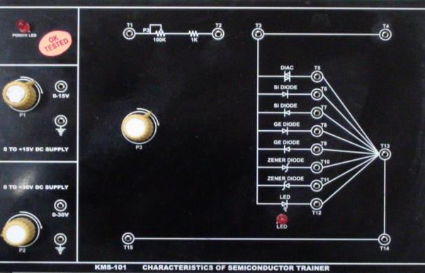
- Basic measurement and characteristics of SCR,TRIAC
- Single / Three phase rectifier and phase control (AC - DC, AC - AC)
- DC Chopper Circuit and Characteristic of IGBT (DC - DC)
- Single / Three Phase Frequency Converter (AC – DC - AC)
- Switching Power Supply Circuit and Characteristics of MOSFET (DC - DC)
- Electronic Ballast circuit (AC - AC)
- Inverter (DC - AC)
- Definition, Insulators, Semiconductors and Conductors, Type of Semiconductors, PN Junction Diode, Transistor PNP & NPN, Power Electronic Devices
- Turn-On Methods of a Thyristor, Gate Triggering Methods, Turn-Off Method
- General Firing Circuit, Resistance Firing Circuit, Resistance-Capacitance Firing Circuit for Half and Full Wave, UJT Oscillator, Synchronized UJT Triggering (Ramp Triggering), Ramp and Pedestal Triggering
- Uncontrolled Rectifiers (Half Wave, Full Wave and Bridge), Firing Circuits for Controlled Rectifiers (using Triangular Comparator, Ramp Comparator, Cosine Firing Scheme, IC-TCA785), Controlled Rectifier (Single Phase Half, Full, Semi Converter and Bridge Rectifiers with R-Load and RL-Load), Applications
- Series Inverter, Parallel Inverter, Bridge Inverter, Applications
- DC-DC Chopper (Introduction, Step-Down Chopper, Step-Up Chopper), AC Chopper, Applications
- Frequency Converter Firing Scheme, Single Phase Frequency Converter, Applications
- AC Voltage Controller Half and Full Wave with R-Load and RL-Load, Application
RELATED PRODUCTS

Automated Sludge Sewage Treatment Plant ENV 004
Rated 0 out of 5

Deep Filter Bed Column ENV 002
Rated 0 out of 5
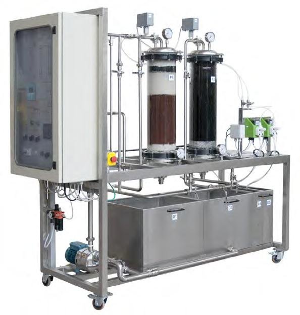
Filtration Pilot Plant ENV 015
Rated 0 out of 5

Microprocessor Trainers 8085
Rated 0 out of 5

Spray Chamber Trainer System ENV 009
Rated 0 out of 5


