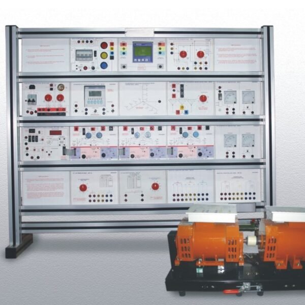
BASIC PID CONTROL TRAINER MODEL PCT 006

– Analog as well as Digital PID control working trainer.
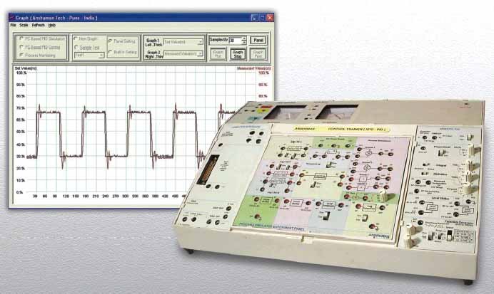
– Facility to monitor behavior of the PID output & process variable either on PC screen or on CRO.
– User settable PID controller Parameters for P, PI, PD & PID operations.
– Enables learning of different processes using simulated building blocks as well as real life processes using replaceable experiment panels.

Item Description

– Graph printing facility for laboratory journal entries.
– Aesthetically designed injection moulded electronic desk (master unit) carrying useful experiment resources like Power supplies, DPMs, Computer Interface, Analog PID controller with central slot to hold various replaceable experiment panels.
– Connection through sturdy 4mm Banana sockets & Patch cords.
– Student workbook & Instructor’s Guide provided with each unit.

Technical Specifications

– Basic Resources on Top board
– Built in power supply
DC supply +/- 12V,500mA.; 1 sine reference for cosine firing 30Vpp max; 17Vdc 500mA unregulated for
driving pulse transformer.
– Display
A) DPM – 2nos.
I) For temp upto 1000C & intensity in Lux (2000) ii) For temp upto 5000C
B) Analog Meter – 2nos. a) Centre zero for display of process error (+9V);
b) For MV/SP (0-2.5V)
– Operating voltage
Switch selectable 220-240Vac +10% 50Hz
– Mechanical Dimensions
a) Master Unit :400mm(W),125mm (H),270mm(D) Net weight : 8Kg. Gross weight : 10Kg.
b) Panel : 215mm(W), 165mm(H), 40mm(D) Net weight : 700gm approx.
– Analog PID (APID) controller with built in low freq. function generator
– Controller selection P,PI,PD,PID with slide switch
– Parameter settings: Integral Time Ti (0.5-25Sec)
Derivative Time Td (0-2Sec)
Proportional Band Pb (5-200%)
Set point (-9V- +9V)
– Operating modes : Fast (X 100/10mSec) for oscilloscope,
Slow ( X 0.1/1Sec) for PC interface.
– 2 No. Level shifter converting process o/p (9V) to 0-2.5V for PC interface & Actuator panel
– Test points for Process Error, Set Point (Rn), Measured Value (Cn), Controller output (Un).
– Built in function generator

-O/p waveform selectable sine, triangular & square.
-O/p freq. range from 0.016Hz to 166Hz, 4 steps & fine control pot.
-Variable amplitude using potentiometer from +9V max.
– PC (P4/XP/ FAT32) based PID controller
– Online monitoring / Data acquisition / PID Software
Self extracting package (CD) works under 98, 20K, XP.
– Operating modes
a) Simulator Mode
Tests data already stored in files (*.txt) & Drawing graph for all P,PI,PD & PID modes.
b) Process Monitoring Mode
Drawing graphs of analog data presented at CH 0 & CH 1 of Computer Interface. Cursors for X & Y axis for measurement & online graphs savings for reproduction
– . Computer Interface Adapter / CIA
Opto-isolated Adaptor to prevent damage to PC parallel port (25 pin LPT) due to wrong connections. Interfaces through 25 pin M to F cable 1mtr Length. P4/XP with parallel port needed but not in scope of supply.
4 ADC channels : 0 to 2.5V full scale.
1 DAC channel : o/p 2.5 V FS.
V to I Function block : Input : 0-2.5Vdc,
Output : 0-20mA or 4-20mA, in 100E load max.
c) PID controller Mode
– PID controller with parameter like Integral Time Ti (0.1-64K) , Sampling Time Ts(0.1- 99.9) ,Derivative Time Td(0.1-99.9) ,Proportional Band Pb(1-999), Derivative Gain Kd(1-999) , Set Value Rn(0-99.9), PID output Upper Limit Uh(0-99.9), PID output Lower Limit Ul (0-99.9), Settable PWM output Cycle Time Ct (0.1-999).
– Facility to set units for output viz. Percentage (%), 0C, Voltage(V) & PWM O/P.
– Optionally experiments with advance process control scheme viz; Ratio, Cascade, feed-forward with user selectable Aux PID, Ratio station & programmable FF transfer function calculator.