AIR FLOW STUDIES APPARATUS Model FM 34
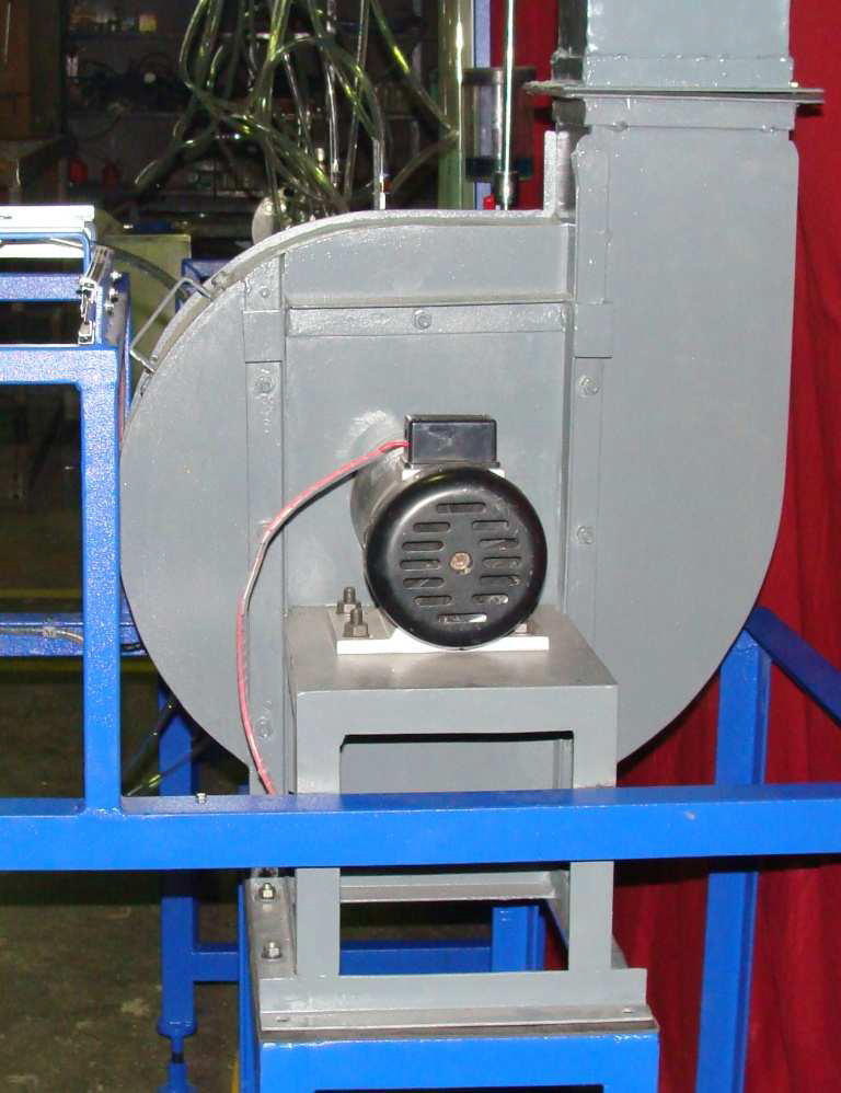
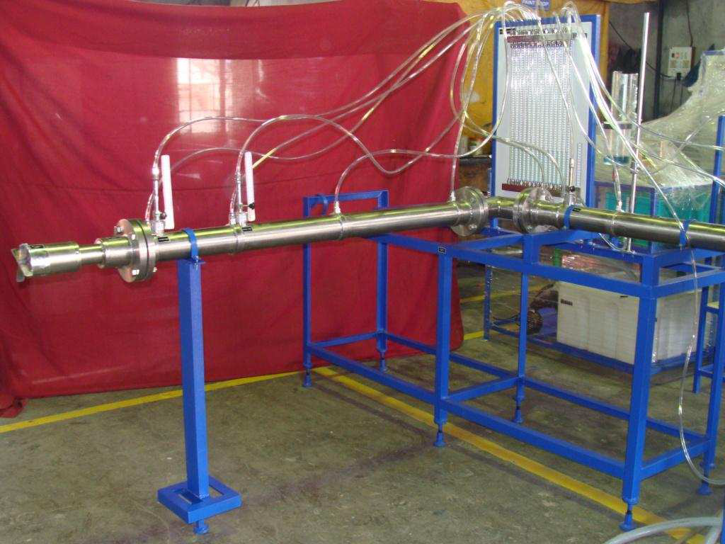
Sci-tech Air Flow Studies Apparatus Model FM 034 is a self-contained and compact unit designed to demonstrate the basic fluid mechanics principles by conducting measurements of important characteristics associated with a typical industrial air distribution system. The apparatus will enable students to study the principles of fluid mechanics by analysing the flows in ducts and jets. The apparatus consists of a long smooth walled stainless-steel pipe with a bell mouth entry connected to the suction side of the centrifugal fan. The bell mouth entry prevents flow separation from the walls of the pipe at the entrance. The turbulence in the pipe is reduced because of the use of suction fan. Flow straightening vanes are provided to minimize formation of vortices resulting in reduction of turbulence in the test pipe. The fan discharge pipe terminates in a flow control damper (for closed circuit operation) or a plate containing an aperture to obtain a jet for measurements. Two nozzles and an orifice plate are provided to measure flow rate by differential static pressure measurements. Static pressure taps are provided along the length of the pipe at equal intervals to measure pressure gradient along the pipe. A bend or mitered cascade elbow can be fitted at the inlet of the pipeline to measure the pressure loss. Provision is made to measure the boundary layer growth and the mean velocity profiles at six stations along the pipe length by traversing the Pitot probe. Arrangement is provided to study the characteristics of the jet flow by traversing the Pitot-static probe in the jet flow. The probe can be traversed in two perpendicular directions at several stations along the length of the jet to study the jet spread or dispersion. Pressures are measured using a 15-tube inclined manometer. The inclined manometer is provided to make sensitive pressure measurements. The complete equipment is mounted on a steel frame having the provision for levelling.
Fluid mechanics is an important subject and has applications in several areas including air conditioning, aerospace, automobile, and industrial air distribution systems. Study of air flows and its measurement is important for understanding the basic principles of fluid mechanics. Sci-tech Air Flow Studies Apparatus Model FM 34 is important equipment for laboratories in certificate level, diploma and degree level courses of mechanical, civil, chemical, aeronautical, environmental and related branches of engineering of any educational institutions.
Sci-tech Air Flow Studies Apparatus Model FM 034 is a self-contained and compact unit designed to demonstrate the basic fluid mechanics principles by conducting measurements of important characteristics associated with a typical industrial air distribution system. The apparatus will enable students to study the principles of fluid mechanics by analysing the flows in ducts and jets. The apparatus consists of a long smooth walled stainless-steel pipe with a bell mouth entry connected to the suction side of the centrifugal fan. The bell mouth entry prevents flow separation from the walls of the pipe at the entrance. The turbulence in the pipe is reduced because of the use of suction fan. Flow straightening vanes are provided to minimize formation of vortices resulting in reduction of turbulence in the test pipe. The fan discharge pipe terminates in a flow control damper (for closed circuit operation) or a plate containing an aperture to obtain a jet for measurements. Two nozzles and an orifice plate are provided to measure flow rate by differential static pressure measurements. Static pressure taps are provided along the length of the pipe at equal intervals to measure pressure gradient along the pipe. A bend or mitered cascade elbow can be fitted at the inlet of the pipeline to measure the pressure loss. Provision is made to measure the boundary layer growth and the mean velocity profiles at six stations along the pipe length by traversing the Pitot probe. Arrangement is provided to study the characteristics of the jet flow by traversing the Pitot-static probe in the jet flow. The probe can be traversed in two perpendicular directions at several stations along the length of the jet to study the jet spread or dispersion. Pressures are measured using a 15-tube inclined manometer. The inclined manometer is provided to make sensitive pressure measurements. The complete equipment is mounted on a steel frame having the provision for levelling.
Specifications
- Centrifugal fan, capacity about 250 LPS at STP.
- Velocity in pipe: 35 m/s (max.)
- Pipe inlet diameter: 80 mm.(approx.)
- Length of pipe: 2.5m ~ 3m.
- Bell mouth entry.
- Interchangeable nozzles (2 Nos.): dia. 50 and 80mm.
- Orifice plate ID: 50mm.
- Jet discharge pipe dia.: 30mm.
- Jet traverse range: 160mm X 600mm.
- Multi-tube inclined manometer, 15 tube, 0.6m long.
- Manometer fluid: Kerosene.
- Bend and mitred cascade elbow.
- Pitot probe.
- Pitot-static probe.
- Probe traverse for duct flow measurements.
- Probe traverse for jet flow measurements.
- Support system.
Technical Specifications
- Centrifugal fan, with speed control:
Max. volumetric flow rate: 1800 m³/h. Max. motor power: 750 W.
- It includes a plate with one orifice at the discharge side of the fan to carry out air jet dispersion practical exercises, orifice diameter: 30 mm.
- Long smooth test pipe, inner diameter 81.4 mm; length: 2500 mm approx. It includes:
Deflector in the inlet to prevent air-separation from the wall of the pipe and reduce the formation of vortices.
- Ten pressure tappings to measure the pressure gradient along the pipe.
- Five stations to use the transverse Pitot tube and to determine the boundary layer growth and the development of velocity profile.
- Two Pitot tubes:
Pitot tube located at the discharge of the fan, attached and properly protected. It can be situated at different distances from the discharge orifice to study free jet velocity profiles: Horizontal: -150…150 mm. Vertical: -150…150 mm. Pitot tube can be located in any of the different points of the test tube to perform an air flow analysis of the velocity profile inside the pipe section. This Pitot tube can also be located at different distances in the pipe to demonstrate the boundary layer growth: Vertical: -24…38 mm.
- Iris diaphragm, diameter: 40 - 97 mm. It includes two pressure tappings. Orifice plate, diameter: 50 mm.
- Two nozzles with different diameters, diameters: 50 and 70 mm.
- Two bends and an angle may be fitted to the test pipe to compare pressure losses in fittings.
- Multi-tube inclinable manometer, which can be inclined to increase its resolution.
It includes: 20 water tubes with a length of 500 mm and inner diameter of 6 mm, and a tank made of PMMA to fill it with water.
- Control panel:
Main switch. ON/OFF Fan switch. Fan speed controller. Fan speed display.
- Cables & Accessories for normal experiments are provided.
Optional: Sci-CalR Computer Control Software & Interface Experiments Possibilities
- Measurement of pressure using manometer.
- Measurement of total pressure using Pitot probe.
- Measurement of flow velocity using Pitot-static probe.
- Measurement of flow rate using nozzles.
- Measurement of flow rate using orifice plate.
- Measurement and understanding of velocity profiles.
- Measurement of boundary layer and velocity profiles in duct flows.
- Study of the effect of Reynolds number in duct flow.
- Measurement of static pressure gradient in duct flow.
- Study of pressure loss – flow rate correlation in duct flow.
- Measurement of velocity profiles in jet flow.
- Measurement of jet spread or dispersion.
- Measurement of pressure loss in duct fittings – bends and mitred cascade elbow.
- Study of the laws of conservation of mass and momentum to describe quantitatively the flows in geometries of practical importance such as ducts, bends, nozzles, orifice and in jets.
Measurements
- Static pressures
- Total pressures.
- Flow velocity.
- Pressure gradient.
- Pressure loss.
- Flow rate.
Services Required:
- Water Supply.
- Electrical Supply, 240/440V,3Ph, 50 Hz.


