Air Cooled ‘Fin Fan’ Heat Exchanger Model THC 006
Home » Products » Air Cooled ‘Fin Fan’ Heat Exchanger Model THC 006
Air Cooled ‘Fin Fan’ Heat Exchanger Model THC 006
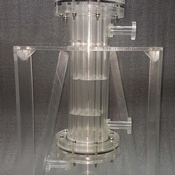
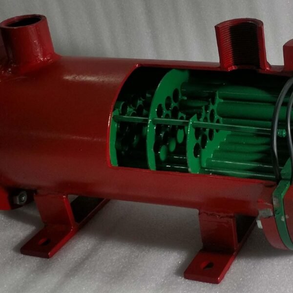
– Made in actual materials allowing study of internal/external construction
– Working model in operational dimensions
– Uses real-time pump for water-pumping
– Durable and easily cleanable model
Item Description
Water shortage and increasing costs, together with more recent concerns about water pollution and cooling tower plumes, have greatly reduced industry’s use of water cooled heat exchangers. Consequently, when further heat integration within the plant is not possible, it is now usual to reject heat directly to the atmosphere, and a large proportion of the process cooling in refineries and chemical plants takes place in Air Cooled Heat Exchangers (ACHEs).
There is also increasing use of Air Cooled Condensers for power stations. The basic principles are the same but these are specialized items and are normally configured as an A-frame or “roof type”. These condensers may be very large—the condensers for a 4000 MW power station in South Africa have over 2300 tube bundles, 288 fans each 9.1 m in diameter and a total plot area 500 m × 70 m.
ACHEs for process plants are normally just called Air coolers, but should not be confused with devices for cooling air (best described as Air Chillers).
The design of an ACHE is more complex than for a Shell and Tube Heat Exchanger, as there are many more components and variables
Technical Specifications
The principle component of an ACHE is the tube bundle, of which there may be many, normally comprising finned tubes terminating in header boxes. The fins are most commonly spirally wound aluminum strips 12.7 × 10⁻³ m or 15.9 × 10⁻³ m high and with 275 to 433 fins/m. There are two main types of wound fin which are usually known as L-fin and G-fin. There are several variations of the former type—single, overlapped, and knurled, but all suffer a high contact resistance, which increases with temperature due to differential expansion between the fin and the core tube. Embedded fins (G-fins) are wound into a groove in the core tube which is then peened back providing a mechanical bond. This gives better heat transfer but requires a thicker core tube. Integral fins extruded from an aluminum sheath are often used for more severe environments, and instead of embedded fins with expensive core tubes. When an exceptionally long life is required in aggressive environments galvanized steel fins can be the best choice, and these frequently use elliptical tubes, which also have improved airflow characteristics. Core tubes may be carbon steel, stainless steel or various alloys and are usually of 25.4 × 10⁻³ m outside diameter. For low pressure or highly viscous applications the tubes can be up to 50.8 × 10⁻³ m diameter. Tube lengths vary to suit the installation, which will often be over a pipe rack, but generally do not exceed 15 m.
Unlike most other pressure vessels an ACHE header box is normally rectangular in cross-section, and the most widely used type has threaded plugs opposite each tube for access. Various cover plate types may be used for low pressures, and for high pressures (up to 500 bar) manifold headers made from thick walled pipe or forged billets are needed. When there could be a large temperature drop across a multi pass tube bundle, split headers may be necessary to accommodate differential expansion between passes. The air is moved over the tubes in a single cross flow pass by axial flow fans, which may be arranged for forced or induced draught. Forced draught is suitable for most applications, has easier maintenance and is by far the more common. Induced draught gives a more even air distribution across the tubes, but requires more power as the fans are in the hot air stream. This latter point also means that induced draught is not suitable for high process temperatures, but is advisable for a close temperature approach as exit velocities are higher and hot air recirculation less likely. For induced draught installations with fan diameters greater than 2.4 m the motor and speed reducer will normally be mounted below the tube bundles, with an extended drive shaft. There are normally at least two fans in each exchanger bay so that significant cooling is maintained in the event of a partial failure, and it is preferable for fans to cover at least 40% of the total bundle face area.
See also different:
Sci-tech Automotive Bus Air-Conditioning Trainer Model AM 003 is designed to enhance student study of bus air conditioner trainer. The trainer is fabricated in aluminum profile rack. Mounted with diesel engine couple to open type reciprocal ty [...]
Model PCT 008-01 : Sci-tech DISPLACEMENT MEASUREMENT USING LVDT TRAINER Model PCT 008-02: Sci-tech PRESURE MEASUREMENT WITH PRESSURE GENERATOR Model PCT 008-03: Sci-tech LOAD MEASUREMENT USING STRAIN GUAGE (LOAD CELL) Model PCT 008- 04: Sci-te [...]