Empowering Education Through Innovation
Empowering Education Through Innovation
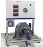
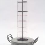
A transparent hollow cylinder made of acrylic is fitted in between the draft tube and the casing for observation of flow. Load is applied to the turbine with the help of rope brake arrangement so that the efficiency of the turbine can be calculated. The set-up is supplied with control panel. A draft tube is fitted on the outlet of the turbine.
The set-up is complete with guide mechanism. Pressure and Vacuum gauges are fitted at the inlet and outlet of the turbine to measure the total supply head on the turbine
Kaplan Turbine is an axial flow reaction turbine named in honour of Dr. B. Kaplan, a German Engineer.
Sci-tech Kaplan Turbine Demonstrator Trainer Model FM 30 is suitable for low head. The power produced by a turbine is proportional to QH. As the head (H) decreases the J discharge (Q) must increase to produce the same power. The present set-up consists of a scroll casing housing a runner. Water enters the turbine through the stationary guide vanes and passes through the runner axially. The runner has a hub and airfoil vanes, which are mounted on it.
In Sci-tech Kaplan Turbine Demonstrator Trainer Model FM 30 the water is fed to the turbine by means of Centrifugal Pump of a hydraulic bench, FM 100F. The runner is directly mounted on one end of a central SS shaft and other end is connected to a brake arrangement. A transparent hollow cylinder made of acrylic is fitted in between the draft tube and the casing for observation of flow. Load is applied to the turbine with the help of rope brake arrangement so that the efficiency of the turbine can be calculated. The set-up is supplied with control panel. A draft tube is fitted on the outlet of the turbine.
The set-up is complete with guide mechanism. Pressure and Vacuum gauges are fitted at the inlet and outlet of the turbine to measure the total supply head on the turbine
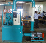
Sci-tech Kaplan Turbine Test Rig FM 30 is designed to show the operation & performance characteristics of Kaplan Turbine. A vertical shaft Kaplan Turbine to develop from 50 Watts to 1000 Watts at 1500 rpm, rope brake arrangement can be coupled for loading.